
Light emitting device

A technology for light-emitting devices and optical devices, which is applied in the directions of lighting devices, lighting device parts, and light source fixing, etc., can solve the problem of difficult cost, service life and safety factor control, inability to achieve 360° optical distribution, and limiting the brightness of lamps and lanterns. structure and other problems, to achieve the effect of improving luminous brightness, low driving voltage, and low cost

Inactive Publication Date: 2012-07-25
OSRAM GMBH
View PDF0 Cites 0 Cited by
  • Summary
  • Abstract
  • Description
  • Claims
  • Application Information

AI Technical Summary

Problems solved by technology

Omni-directional lights constructed in this way have a large number of LED lights and require high driving voltages for this, so it is difficult to control them in terms of cost, lifetime and safety factor
Another existing omnidirectional luminaire includes a light source and a complex lens for the light source to achieve 360° optical distribution. Due to this complex structure, the light source cannot be freely replaced, and to a certain extent limits The brightness and structure of the luminaire, which in turn cannot even achieve a true 360° optical distribution

Method used


Image

  • Light emitting device
  • Light emitting device
  • Light emitting device

Examples


Embodiment Construction

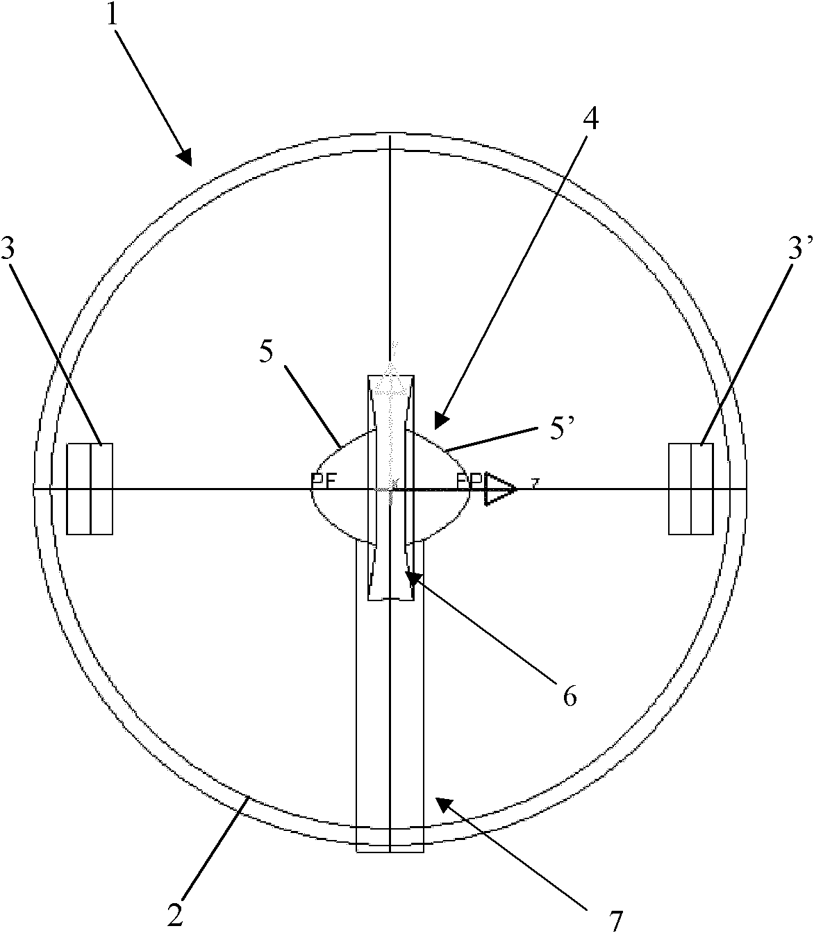
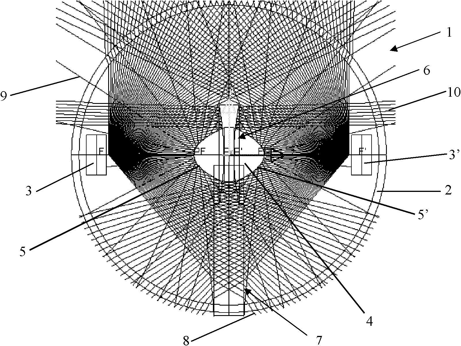
[0023] figure 1 A front view of a lighting device 1 according to the present invention is shown, which includes a lamp housing 2, a pair of light sources 3 and 3' and an optical device such as a reflector 4 mounted on an optical device holder 7. At least one reflector 4 arranged between the paired light sources 3, 3' is designed corresponding to the paired light sources 3, 3' to adjust, for example, reflect the direction of part of the light beams from the light sources 3, 3', to achieve the full beam direction It emits in all directions through the lamp housing 2 . In this embodiment, the light sources 3 and 3' are a pair of light sources that are centered on the reflector light 4 and are installed facing each other in the diameter direction of the spherical lamp housing 2, and the reflector 4 is located in the lamp housing 2 The position of the center of the ball. Here, the reflector 4 is formed from a first region and a second region. In the first area there are ellipsoi...


PUM


Abstract

The invention relates to a light emitting device (1), which is characterized by comprising a lamp shell (2), at least one pair of pairwise light sources (3 and 3') and at least one optical device (4). The pairwise light sources are disposed in the lamp shell (2). Each optical device (4) is disposed between one pair of the pairwise light sources (3 and 3'). The optical devices (4) are designed in correspondence to the pairwise light sources (3 and 3') to adjust, such as, light beams, reflected from the light sources (3 and 3') to the optical devices, so that the light beams are emitted omni-directionally through the lamp shell (2). By means of the light emitting device, 360-degree omni-directional distribution of light can be realized, and even distribution of the light can also be realized. In addition, the light emitting device has the advantages of high brightness, low cost, low drive voltage, high optical efficiency, long service life and high safety coefficient.

Description

technical field [0001] The invention relates to a light emitting device, in particular to an omnidirectional light emitting device. Background technique [0002] Many omnidirectional lights or omnidirectional lights are disclosed in the prior art. In the known technology, some omnidirectional lamps must be composed of LED lamps through simple spatial combination. An omnidirectional lamp constructed in this way has a large number of LED lamps and requires a high driving voltage for this, so it is difficult to control it in terms of cost, service life and safety factor. Another existing omnidirectional luminaire includes a light source and a complex lens for the light source to achieve 360° optical distribution. Due to this complex structure, the light source cannot be freely replaced, and to a certain extent limits The brightness and structure of the luminaire, and then even cannot achieve a true 360° optical distribution. Contents of the invention [0003] Therefore, th...

Claims


Application Information

Patent Timeline
Patent Type & Authority Applications(China)
IPC IPC(8): F21V7/09F21V19/00
Inventor 林晶曾军华兰挺彪罗承旸
Owner OSRAM GMBH
Learn More