Detection device and method for surface defects

A defect detection and defect technology, applied in the direction of optical test defects/defects, etc., can solve the problems of low detection efficiency, slow speed, complex surface background of metal machining parts, etc.

Active Publication Date: 2014-10-15
HANS LASER TECH IND GRP CO LTD +1
View PDF6 Cites 7 Cited by
  • Summary
  • Abstract
  • Description
  • Claims
  • Application Information

AI Technical Summary

Problems solved by technology

The traditional detection method is to detect defects manually. This method is slow, the detection efficiency is low, and subtle defects cannot be detected visually.
Moreover, during the processing of metal machined parts, regular twill lines or patterns are generally formed on the surface, resu

Method used


Image

  • Detection device and method for surface defects
  • Detection device and method for surface defects
  • Detection device and method for surface defects

Examples


Embodiment Construction

[0035] In order to facilitate the understanding of the present invention, the present invention will be described more fully below with reference to the associated drawings. Preferred embodiments of the invention are shown in the accompanying drawings. However, the present invention can be embodied in many different forms and is not limited to the embodiments described herein. On the contrary, these embodiments are provided to make the understanding of the disclosure of the present invention more thorough and comprehensive.

[0036] It should be noted that when an element is referred to as being “fixed” to another element, it can be directly on the other element or there can also be an intervening element. When an element is referred to as being "connected to" another element, it can be directly connected to the other element or intervening elements may also be present.

[0037] Unless otherwise defined, all technical and scientific terms used herein have the same meaning as...


PUM


Abstract

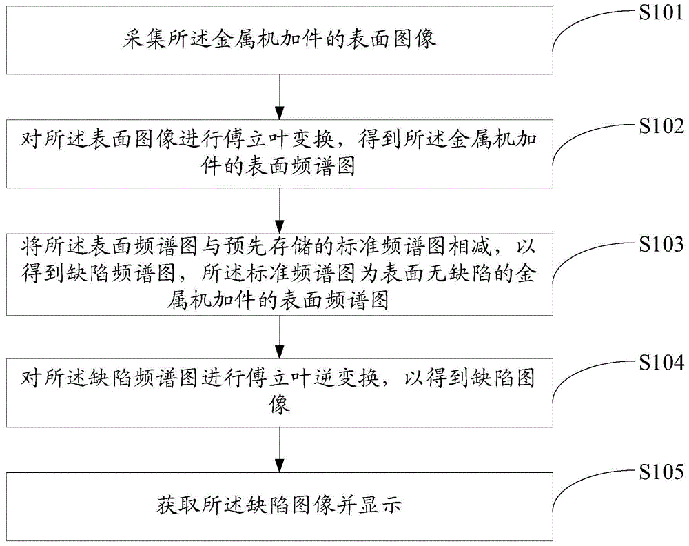
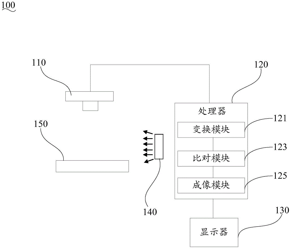
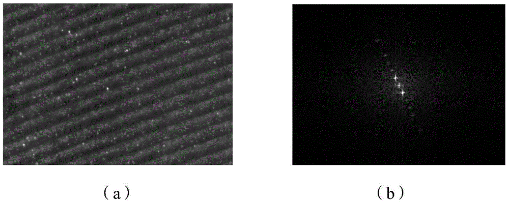
The invention provides a detection method for surface defects. The detection method for surface defects comprises the following steps: the surface frequency spectrum of a metal machining part to be detected and the surface frequency spectrum of a metal machining part free of surface defects are subtracted, so as to obtain a frequency spectrum of defects; the frequency spectrum of defects is actually the frequency spectrum on which the frequency spectrum of the surface background of the metal machining part to be detected is removed; therefore, when the inverse Fourier transform is conducted on the frequency spectrum of the defects, the surface image on which the surface background of the metal machining part to be detected is removed is obtained; the surface image is displayed, the situation that whether the surface of the metal machining part to be detected has defects or not and the distribution of the defects can be clearly distinguished. Therefore, the detection device and the detection method for the surface defects can weaken the interferences of the surface background of the metal machining part to the detection process; the effect of the defect detection is improved and the speed of defect detection is increased. Moreover, the invention further provides a detection device for the surface defects.

Description

technical field [0001] The invention relates to defect detection technology, in particular to a surface defect detection device and method. Background technique [0002] Anodizing is a common processing technology for metal machined parts. The air bubbles generated during the anodizing process may solidify on the metal surface, thereby affecting the quality of metal machined parts. The traditional detection method is to detect defects manually. This method is slow, the detection efficiency is low, and subtle defects cannot be detected visually. Moreover, during the processing of metal machined parts, regular twill lines or patterns are generally formed on the surface, resulting in complex surface backgrounds of metal machined parts. However, when manually detecting defects, the complex background on the surface of the metal machined parts will affect the identification of defects, which makes the effect of defect detection poor and the detection efficiency is not high. Co...

Claims


Application Information

Patent Timeline
IPC IPC(8): G01N21/88
Inventor 舒远李玉廷王光能文茜米野丁兵高云峰
Owner HANS LASER TECH IND GRP CO LTD
Why Eureka
Try Eureka