Plane material surface defect detection device and detection module thereof
A defect detection and planar technology, which is applied in the direction of optical testing for defects/defects, can solve the problems of long product length, small area, large ratio of detection range size, etc., and achieve the effect of convenient installation
- Summary
- Abstract
- Description
- Claims
- Application Information
AI Technical Summary
Problems solved by technology
Method used
Image
Examples
no. 1 example
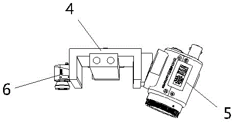
[0034] Such as figure 1 Shown is a schematic structural diagram of an embodiment of a surface defect detection module for planar materials of the present invention. The planar material surface defect detection module of the present embodiment includes a mount 4, and a CCD image sensor 5 for imaging the planar material surface and a dot matrix laser 6 for calibrating the image data collected by the CCD image sensor 5 are installed on the mount 4 .
[0035] Preferably, the CCD image sensor 5 and the dot-matrix laser 6 of this embodiment are respectively located on both sides of the mounting base 4 , and the mounting base 4 is provided with sliding holes for matching with the sliding guide rod 3 for easy installation.
[0036] Preferably, the CCD image sensor 5 and / or the dot-matrix laser 6 are rotatably mounted on the mount 4, and the rotation axis of the CCD image sensor 5 and / or the dot-matrix laser 6 is parallel to the axis of the sliding hole. The CCD of this embodiment Th...
no. 2 example
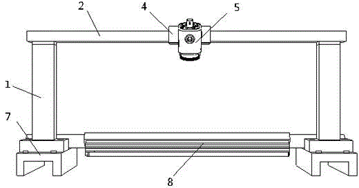
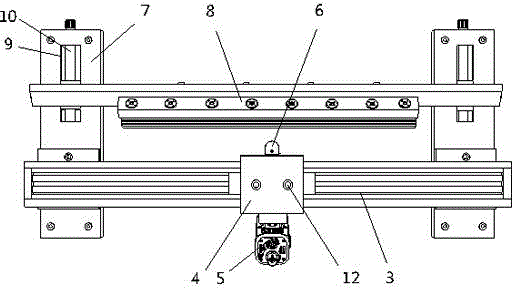
[0039] Such as figure 1As shown, it is a schematic structural diagram of the first embodiment of the surface defect detection device for planar materials of the present invention. The device for detecting surface defects of planar materials in this embodiment includes a main frame, a linear light source installed on the main frame, and at least one detection module as described in the first embodiment installed on the main frame. The detection module of this embodiment is set for one. The main body frame includes two columns 1 on both sides and a beam 2 fixedly installed on the two columns 1. The beam 2 is provided with a sliding guide rod 3 matched with a sliding hole. The two columns 1 are respectively provided with linear light source installation seats 7, and the two ends of the linear light source 8 are respectively installed on the two linear light source installation seats 7, and there is a set between the linear light source installation seat 7 and the linear light so...
no. 3 example
[0045] Such as Figure 5 As shown, it is a functional block diagram of the control system of the second embodiment of the surface defect detection device for planar materials of the present invention. The device for detecting surface defects of planar materials in this embodiment includes a main frame, a linear light source installed on the main frame, and at least one detection module as described in the first embodiment installed on the main frame. The main body frame includes two columns 1 on both sides and a beam 2 fixedly installed on the two columns 1. The beam 2 is provided with a sliding guide rod 3 matched with a sliding hole. The two columns 1 are respectively provided with linear light source installation seats 7, and the two ends of the linear light source 8 are respectively installed on the two linear light source installation seats 7, and there is a set between the linear light source installation seat 7 and the linear light source 8 for adjusting the linear ligh...
PUM
 Abstract
Description
Claims
Application Information
 - R&D
- Intellectual Property
- Life Sciences
- Materials
- Tech Scout
- Unparalleled Data Quality
- Higher Quality Content
- 60% Fewer Hallucinations
Browse by: Latest US Patents, China's latest patents, Technical Efficacy Thesaurus, Application Domain, Technology Topic, Popular Technical Reports.
© 2025 PatSnap. All rights reserved.Legal|Privacy policy|Modern Slavery Act Transparency Statement|Sitemap|About US| Contact US: help@patsnap.com


