
Weld defect detection method and device, electronic equipment and storage medium

A technology for defect detection and detection, which is applied in the direction of analyzing solids, instruments, and analysis materials using sound waves/ultrasonic waves/infrasonic waves. It can solve the problems of small detection range, prone to missed detection, and low detection efficiency. The effect of improving efficiency and improving horizontal resolution

Active Publication Date: 2021-10-01
BEIHANG UNIV
View PDF4 Cites 1 Cited by
  • Summary
  • Abstract
  • Description
  • Claims
  • Application Information

AI Technical Summary

Problems solved by technology

The traditional ultrasonic body wave detection is a point-by-point screening, the detection range is small, and the detection efficiency is low
Undoubtedly, if traditional ultrasonic body waves are used to detect defects in long weld structures in metal welded components, the workload is huge and prone to missed inspections

Method used


Image

  • Weld defect detection method and device, electronic equipment and storage medium
  • Weld defect detection method and device, electronic equipment and storage medium
  • Weld defect detection method and device, electronic equipment and storage medium

Examples


Embodiment Construction

[0057] In order to more clearly understand the above objects, features and advantages of the present disclosure, the solutions of the present disclosure will be further described below. It should be noted that, in the case of no conflict, the embodiments of the present disclosure and the features in the embodiments can be combined with each other.

[0058] In the following description, many specific details are set forth in order to fully understand the present disclosure, but the present disclosure can also be implemented in other ways than described here; obviously, the embodiments in the description are only some of the embodiments of the present disclosure, and Not all examples.

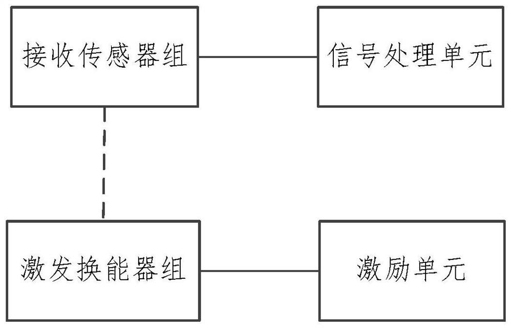
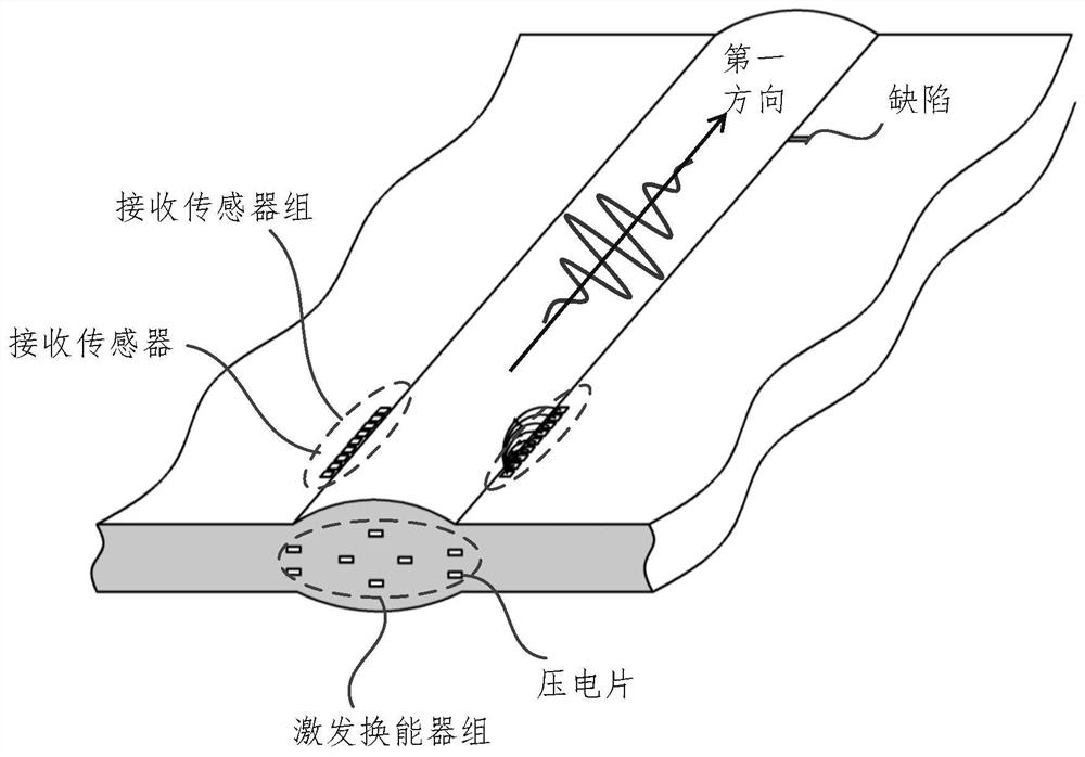
[0059] figure 1 A structural block diagram of a weld defect detection system provided by an embodiment of the present disclosure; figure 2 for will figure 1 Schematic diagram of the structure of the excitation transducer group and the receiving sensor group arranged on the component including...


PUM


Abstract

The invention relates to a weld defect detection method and device, electronic equipment and a storage medium. The method comprises the steps of determining a first vibration signal corresponding to a target sensor based on a detection signal of the target sensor; determining a first vibration signal corresponding to each non-target sensor based on the detection signal of each non-target sensor; based on the first vibration signals corresponding to the non-target sensors, determining second vibration signals of reference waves corresponding to the non-target sensors at target sensor setting positions; superposing the first vibration signal corresponding to the target sensor and the second vibration signal of each reference wave at the setting position of the target sensor to obtain a superposed third vibration signal; and determining weld defect data in the to-be-detected component based on the superposed third vibration signal. The device can be used for detecting local defects in a long welding seam structure with high transverse resolution capability and high axial positioning precision, and can realize remote in-service quality monitoring.

Description

technical field [0001] The present disclosure relates to the field of welding technology, and in particular to a method, device, electronic equipment and storage medium for detecting weld defects. Background technique [0002] With the rapid development of modern industrial technology, metal welded components are widely used in engineering fields such as aerospace, shipbuilding, oil and gas pipelines, and nuclear power. In metal welded components, the long weld structure is the area of ​​stress concentration. Among them, weld hot spots (such as welding caps, welding toes, weld nuggets, fusion zones, heat-affected zones, etc.) are prone to slag inclusions, pores, cracks, incomplete fusion / penetration, pits, undercuts, weld tumors, etc. Multiple morphological defects. The initiation and expansion of defects will reduce the fatigue life and fatigue strength of welded joints, degrade their mechanical properties and reduce the reliability of components. Therefore, it is partic...

Claims


Application Information

Patent Timeline
IPC IPC(8): G01N29/04
CPCG01N29/04G01N2291/267
Inventor 余旭东秦荣
Owner BEIHANG UNIV
Learn More