Electrical component

A technology for electrical components and wires, applied in the field of electrical components, can solve the problems of difficult wiring of electrical wiring H, etc., and achieve the effects of less interference, increased freedom in the lead-out direction, and easy winding.

Active Publication Date: 2014-10-15
ALPS ALPINE CO LTD
View PDF3 Cites 0 Cited by
  • Summary
  • Abstract
  • Description
  • Claims
  • Application Information

AI Technical Summary

Problems solved by technology

[0006] However, in the electrical component SW described in Patent Document 1, the electrical wiring H is led out only in one direction in terms of prod

Method used


Image

  • Electrical component
  • Electrical component
  • Electrical component

Examples


no. 1 approach ]

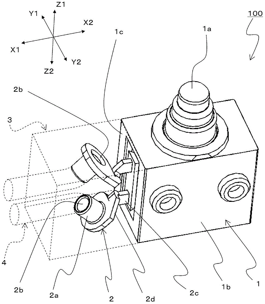
[0043] Hereinafter, the electrical component 100 in the first embodiment will be described.

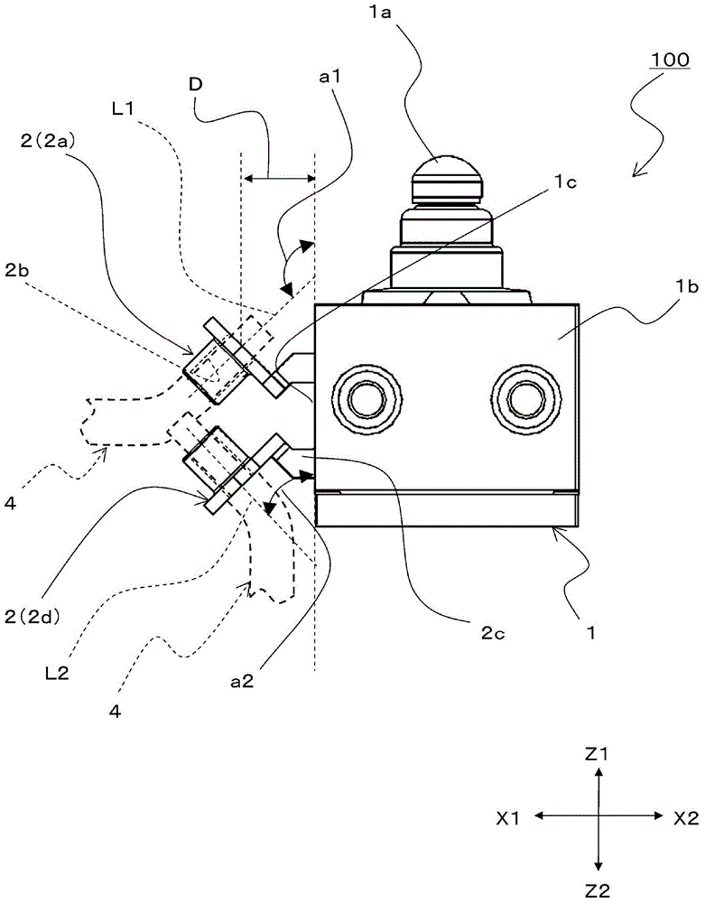
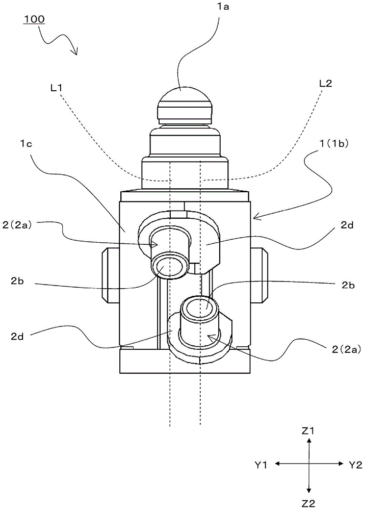
[0044] First, use Figure 1 to Figure 3 The structure of the electrical component 100 in this embodiment is demonstrated. figure 1 It is a perspective view showing the appearance of the electrical component 100 in this embodiment. exist figure 1 In the figure, the shape of the sealing member 3 differs depending on the direction in which the electric wires 4 connected to the connection terminal 2 are drawn out, and therefore the sealing member 3 and the electric wires 4 are only schematically shown by dotted lines. figure 2 is from figure 1 The shown Y2 direction side is a side view of the state which looked at the electric component 100 in this embodiment. exist figure 2 In , for ease of description, the sealing member 3 is not described. image 3 is from figure 1 The shown X1 direction side is a side view of the state which looked at the electrical component 100 in this ...


PUM


Abstract

The present invention provides an electrical component in which winding of electric wires is free. The electrical component (100) comprises a frame (1) and two connecting terminals (2) which are adjacent and protruded from the frame (1) therein, wherein each connecting terminal (2) has a cylindrical part (2a) provided with an inserting hole (2b) in which an electric wire (4) can insert, the cylindrical parts (2a) of the adjacent two connecting terminals (2) are protruded at different angles relative to the frame (1), and the cylindrical parts (2a) are separated from the frame (1) in the way that the electric wire (4) can insert from either one end side of the inserting hole (2b) or the other end side of the inserting hole (2b).

Description

technical field [0001] The present invention relates to an electrical component capable of being electrically connected to the outside through an electric wire, and particularly relates to an electrical component (for example, a switchgear) having a degree of freedom in winding the electric wire. Background technique [0002] For example, electrical components mounted on automobiles and the like are often connected via electric wires. In addition, recently, the electronicization of automobiles has progressed, and in order to mount more electrical components in the conventionally limited space, electrical components with more degrees of freedom in the winding of electric wires are required. [0003] An electrical component described in Patent Document 1 below is known as an electrical component having an electric wire. Below, use Figure 8 An electrical component having an electric wire described in Patent Document 1 will be described. Figure 8 It is a figure which shows th...

Claims


Application Information

Patent Timeline
IPC IPC(8): H01H13/02
Inventor 二宫伸之
Owner ALPS ALPINE CO LTD
Why Eureka
Try Eureka