

Double-half-bridge injection phase-locking power synthesis high-pressure sodium lamp
A technology of injecting phase-locked, high-pressure sodium lamps, applied in lighting devices, light sources, electrical components, etc., can solve problems such as non-linear intermodulation power imbalance, avoid power imbalance due to oscillation frequency changes, prolong service life, and improve lighting quality. Effect
Active Publication Date: 2014-10-15
浙江龙鹰光电科技有限公司
View PDF5 Cites 2 Cited by
- Summary
- Abstract
- Description
- Claims
- Application Information
AI Technical Summary
Problems solved by technology
However, it is required that the phase of the power synthesis oscillating voltage be consistent to overcome the imbalance of nonlinear intermodulation power
Method used
View moreImage
Smart ImageViewing Examples

Examples
Embodiment
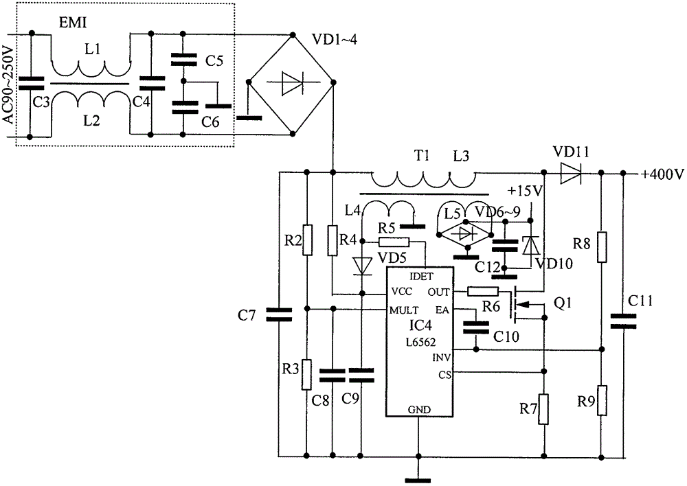
[0027] Embodiment AC power supply AC90~250V, power factor correction APFC output DC400V, power factor 0.98, double half-bridge inverter current 0.72A, ignite one 250W or two 100W high-pressure sodium lamp G, the efficiency is 86%, the light is stable, no flicker .
Login to View More PUM
 Abstract
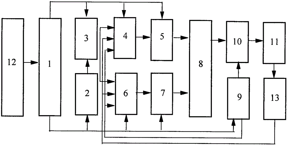
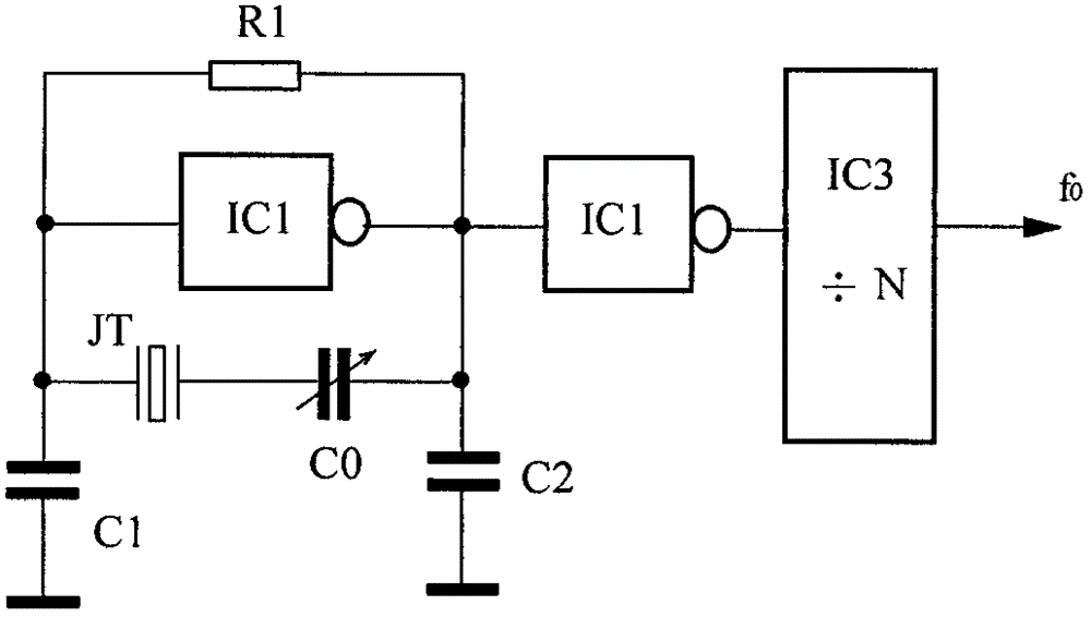
The invention relates to the technical field of electric light source illumination and specifically discloses a double-half-bridge injection phase-locking power synthesis high-pressure sodium lamp. RC oscillators of two self-sustained oscillation chips 4, 6 are connected with a resistor R4 and a capacitor C5 for synchronous oscillation. The self-sustained oscillation chip 4 and a half-bridge inverter A output power transformer T1 and the self-sustained oscillation chip 6 and a half-bridge inverter B output power transformer T2 are fed into an addition coupler in a reverse-phase manner. The synthesized power is fed into a lamp tube trigger circuit for turning a high-pressure sodium lamp on. Signals of a reference crystal oscillator are injected into the RC oscillators of the two self-sustained oscillation chips 4, 6 through a frequency divider for phase locking, and thus large-power illumination is achieved, and luminance declination caused by power unbalance resulted from oscillation frequency change since temperature rise of a device is too high is avoided. Sawtooth-wave signals of a frequency modulation signal generator are accessed to the RC oscillators of the two self-sustained oscillation chips 4, 6 for suppressing light scintillation in a frequency modulation way. The high-pressure sodium lamp is suitable for large-power high-pressure sodium lamp illumination occasions.
Description
technical field [0001] The invention relates to the technical field of electric light source lighting, in particular to a double half-bridge injection phase-locked power synthesis high pressure sodium lamp. Background technique [0002] In the prior art, electronic ballasts generally use LC or RC oscillators as the high-pressure sodium lamp light source, and the oscillation frequency generated is affected by the poor stability of temperature changes, and the power is not stable enough, resulting in a decrease in light intensity. Although the structure is simple and the cost is low. In order to obtain high-power lighting, the current of the device must be increased, which will cause the power consumption of the oscillating power tube to increase sharply and the temperature will rise too high, resulting in a change in the oscillation frequency. As a result, the power amplitude of the light will be unbalanced as the frequency changes. At the same time, when the large current pa...
Claims
Login to View More Application Information
Patent Timeline
 Patent Type & AuthorityApplications(China)
IPC IPC(8): H05B41/292
Inventor阮树成阮雪芬
Owner浙江龙鹰光电科技有限公司