A valve buffer feeding device

A valve and material storage technology, which is applied in the field of valve buffer feeding devices, can solve problems such as affecting valve quality, valve damage, and collision, and achieve the effect of ensuring production and inspection quality and avoiding rigid collisions.

Active Publication Date: 2016-09-14
WUXI SHUANGYI PRECISION MACHINERY
View PDF7 Cites 0 Cited by
  • Summary
  • Abstract
  • Description
  • Claims
  • Application Information

AI Technical Summary

Problems solved by technology

[0002] The role of the valve is to input fuel into the engine and discharge exhaust gas. The valve plays a certain role in sealing. It is T-shaped. In order to ensure the normal operation of the engine, the quality of the valve is very important. During the production process of the valve, it is necessary to For quality inspection, in order to improve the detection efficiency, the existing valve detection has been automated, and it is bound to require the valve to realize automatic feeding. Due to the limitation of the shape of the valve, the existing valve feeding usually adopts vibration feeding. During the vibration feeding process, due to the valve The rigidity of the valves, the collision between the valves will cause damage to the valves and affect the quality of the valves, especially for the processed valves, the use of vibration feeding can no longer guarantee the quality requirements of the valves, and the use of other feeding methods will also produce valve movement Collision in process

Method used


Image

  • A valve buffer feeding device
  • A valve buffer feeding device
  • A valve buffer feeding device

Examples


Embodiment Construction

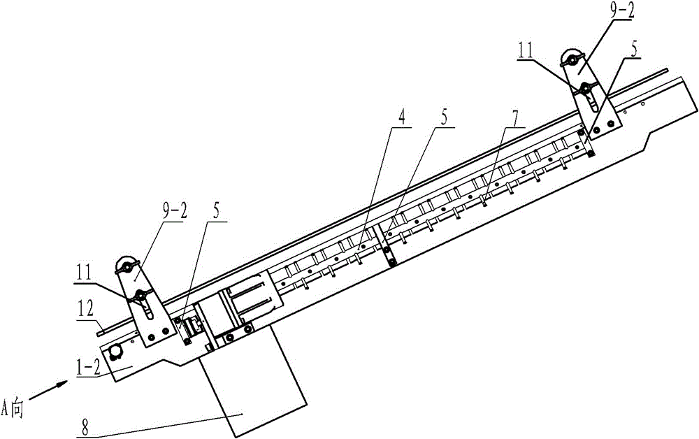
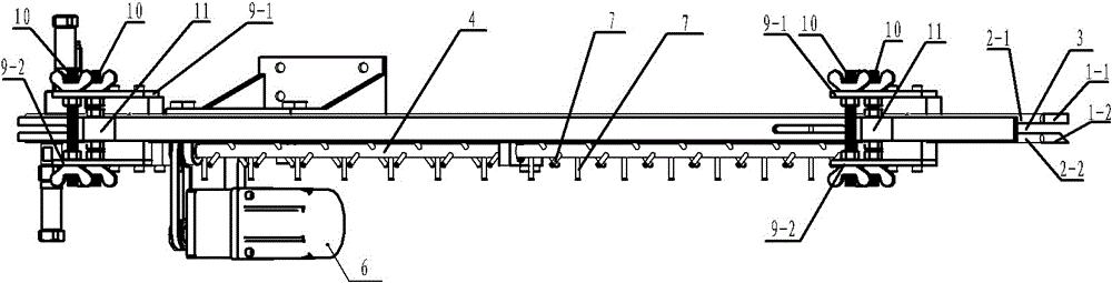
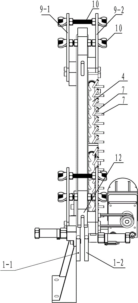
[0012] See figure 1 , figure 2 , image 3 , Figure 4 and Figure 5 , a buffer feeding device for an intake valve, which includes material receiving plates 1-1 and 1-2 on both sides, and the upper ends of the material receiving plates 1-1 and 1-2 are respectively provided with storage rods 2-1 and 2-2 , forming a material channel 3, a rotating shaft 4 is provided corresponding to the lower ends of the material receiving plates 1-1, 1-2, the rotating shaft 4 is supported by the bearing seat 5, the rotating shaft 4 is connected to the driving motor 6, and a plurality of stops are arranged on the rotating shaft 4 Material strips 7, adjacent blocking strips 7 are arranged crosswise, the rotation of the rotating shaft 4, the adjacent cross-arranged blocking strips form sequential opening and closing, push down the valves one by one, and realize the feeding of the valves one by one, because the valves pass through the blocking strips one by one Pushing it down effectively avoid...


PUM


Abstract

The invention provides a valve buffer feeding device, which realizes automatic material feeding in the process of valve production and detection, improves production efficiency, effectively avoids rigid collision between valves in the material feeding process, and ensures the quality of valve production and detection, which includes The material receiving plates on both sides, the upper ends of the material receiving plates are respectively provided with material storage rods to form a material channel, and it is characterized in that: a rotating shaft is arranged corresponding to the lower end of the material receiving plate, and a plurality of stoppers are arranged on the rotating shafts strips, and the adjacent said retaining strips are arranged crosswise.

Description

technical field [0001] The invention relates to the technical field of mechanical manufacturing inspection, in particular to a valve buffer feeding device. Background technique [0002] The role of the valve is to input fuel into the engine and discharge exhaust gas. The valve plays a certain role in sealing. It is T-shaped. In order to ensure the normal operation of the engine, the quality of the valve is very important. During the production process of the valve, it is necessary to For quality inspection, in order to improve the detection efficiency, the existing valve detection has been automated, and it is bound to require the valve to realize automatic feeding. Due to the limitation of the shape of the valve, the existing valve feeding usually adopts vibration feeding. During the vibration feeding process, due to the valve The rigidity of the valves, the collision between the valves will cause damage to the valves and affect the quality of the valves, especially for the...

Claims


Application Information

Patent Timeline
Patent Type & Authority Patents(China)
IPC IPC(8): B65G47/74
Inventor 林安徽
Owner WUXI SHUANGYI PRECISION MACHINERY
Why Eureka
Try Eureka