Annular workpiece guide device

一种导料装置、环状工件的技术,应用在输送机物件、运输和包装等方向,能够解决自动化程度低、操作麻烦、环状工件传送加工效率和传送加工质量难以得到保证等问题,达到结构设计合理、提高加工自动化程度的效果

Inactive Publication Date: 2020-12-22
郭煜萍
View PDF0 Cites 0 Cited by
  • Summary
  • Abstract
  • Description
  • Claims
  • Application Information

AI Technical Summary

Problems solved by technology

The ring-shaped workpiece is a commonly used workpiece now. During the production and processing process of the ring-shaped workpiece, it needs to go through the processing steps of feeding, cutting and grinding. During the above processing steps, the ring-shaped workpiece needs to be processed according to the The above-mentioned processing steps are transmitted sequentially. During the transmission process of the ring-shaped workpiece, in order to facilitate the continuous production and processing of the workpiece in the subsequent process, and to meet the consistency of the transmission and processing speed of the workpiece in the previous process and the subsequent process, It is necessary to carry out combined transmission of circular workpieces. The existing workpiece combined transmission mechanism has complex structure and troublesome operation, and it is difficult to realize the combined transmission of circular workpieces in a smooth and orderly manner. Finally, it is difficult to guide and transfer the ring-shaped workpieces one by one according to the processing needs of the subsequent process. The degree of automation of the ring-shaped workpiece transfer processing is low, which makes it difficult to guarantee the transfer processing efficiency and transfer processing quality of the ring-shaped workpieces, which cannot meet the needs of production and processing. use needs

Method used


Image

  • Annular workpiece guide device
  • Annular workpiece guide device
  • Annular workpiece guide device

Examples


Embodiment Construction

[0012] In order to further describe the present invention, the specific implementation of a ring-shaped workpiece feeding device will be further described below in conjunction with the accompanying drawings. The following examples are explanations of the present invention and the present invention is not limited to the following examples.

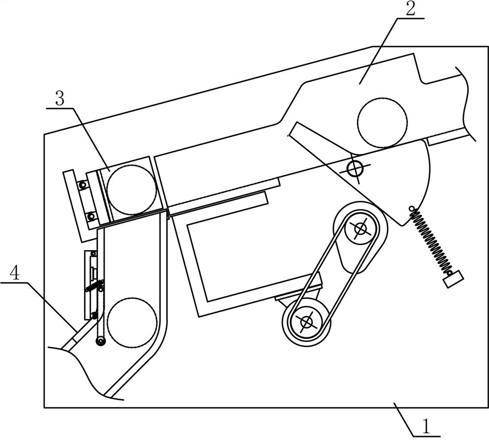
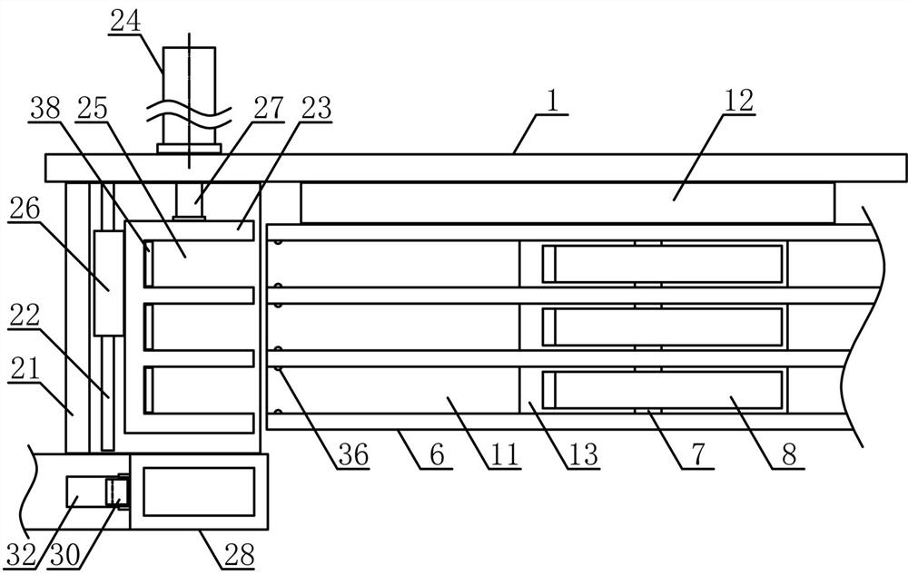
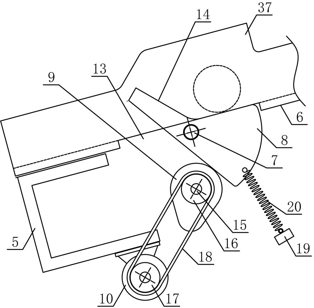
[0013] Such as figure 1 with figure 2 As shown, a ring-shaped workpiece material guide device of the present invention includes a material guide bracket 1, a material transmission mechanism 2, a material pushing mechanism 3 and a material blanking mechanism 4, and the material transmission mechanism 2 and the material pushing mechanism 3 are from top to bottom along the inclined direction. The bottom is fixedly arranged on one side of the material guide bracket 1 in turn, and the blanking mechanism 4 is vertically fixedly arranged on the material guide bracket 1 on one side of the pushing mechanism 3 . Such as image 3 As shown, the mate...


PUM


Abstract

The invention discloses an annular workpiece guide device, and belongs to the field of workpiece transferring and machining equipment. A plurality of guide sliding grooves are formed in the upper sideof a transfer support in the oblique direction in sequence; a plurality of guide rotation plates are vertically and fixedly arranged on a guide rotation shaft in the horizontal direction in sequence;a plurality of bearing clamping grooves with the size matched with the size of the guide sliding grooves are uniformly formed in a push support along the transfer support; a push piston rod at the output end of a horizontal thrust air cylinder is fixedly connected with the middle of one side of the push support; a material guide pipe is vertically and fixedly arranged on the guide support which is arranged on one side of the bearing support; and a blanking baffle is arranged in a baffler swing groove in one side of the lower portion of the material guide pipe. The structural design is reasonable; it can be achieved that a plurality of annular workpieces are combined and transferred; it can be ensured that the annular workpieces are unloaded and transferred one by one; the degree of automation of transferring and machining of the workpieces is improved; and the requirements for machining and use are met.

Description

technical field [0001] The invention belongs to the field of workpiece conveying and processing machinery, and in particular relates to a ring-shaped workpiece material guide device, which is mainly used for continuous joint-path conveyance of ring-shaped workpieces. Background technique [0002] The mechanical workpiece is a single piece that makes up the machine and its inseparability. It plays an important role in the automation industry. The mechanical workpiece includes the connection of parts, the supporting parts, the lubricating lubrication system and the sealing Components, components of the transmission system that transmits motion and energy, there are many types of workpieces, which can be mainly divided into: shaft sleeve workpieces, disc cover workpieces, fork bracket workpieces and box body workpieces according to the function and shape of the workpiece. The main part of the structure of the shaft sleeve workpiece is a coaxial rotary body, which mainly plays t...

Claims


Application Information

Patent Timeline
Patent Type & Authority Applications(China)
IPC IPC(8): B65G47/24B65G47/82B65G47/88
CPCB65G47/24B65G47/82B65G47/8815
Inventor 郭煜萍
Owner 郭煜萍
Why Eureka
Try Eureka