Combined guiding mechanism for annular workpieces

A ring-shaped workpiece and pusher mechanism technology, applied in the direction of conveyor objects, transportation and packaging, etc., can solve the problems of low degree of automation, troublesome operation, complex structure, etc., achieve the effect of reasonable structure design and improve the degree of processing automation

Active Publication Date: 2019-11-15
滨州市沾化区蓝乔生物科技有限公司
View PDF7 Cites 8 Cited by
  • Summary
  • Abstract
  • Description
  • Claims
  • Application Information

AI Technical Summary

Problems solved by technology

The ring-shaped workpiece is a commonly used workpiece now. During the production and processing process of the ring-shaped workpiece, it needs to go through the processing steps of feeding, cutting and grinding. During the above processing steps, the ring-shaped workpiece needs to be processed according to the The above-mentioned processing steps are transmitted sequentially. During the transmission process of the ring-shaped workpiece, in order to facilitate the continuous production and processing of the workpiece in the subsequent process, and to meet the consistency of the transmission and processing speed of the workpiece in the previous process and the subsequent process, It is necessary to carry out combined transmission of circular workpieces. The existing workpiece combined transmission mechanism has complex structure and troublesome operation, and it is difficult to realize the combined transmission of circular workpieces in a smooth and orderly manner. Finally, it is difficult to guide and transfer the ring-shaped workpieces one by one according to the processing needs of the subsequent process. The degree of automation of the ring-shaped workpiece transfer processing is low, which makes it difficult to guarantee the transfer processing efficiency and transfer processing quality of the ring-shaped workpieces, which cannot meet the needs of production and processing. use needs

Method used


Image

  • Combined guiding mechanism for annular workpieces
  • Combined guiding mechanism for annular workpieces
  • Combined guiding mechanism for annular workpieces

Examples


Embodiment Construction

[0017] In order to further describe the present invention, a specific implementation of a material-combining and guiding mechanism for ring-shaped workpieces will be further described below in conjunction with the accompanying drawings. The following examples are explanations of the present invention and the present invention is not limited to the following examples.

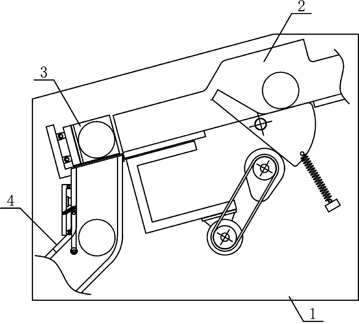
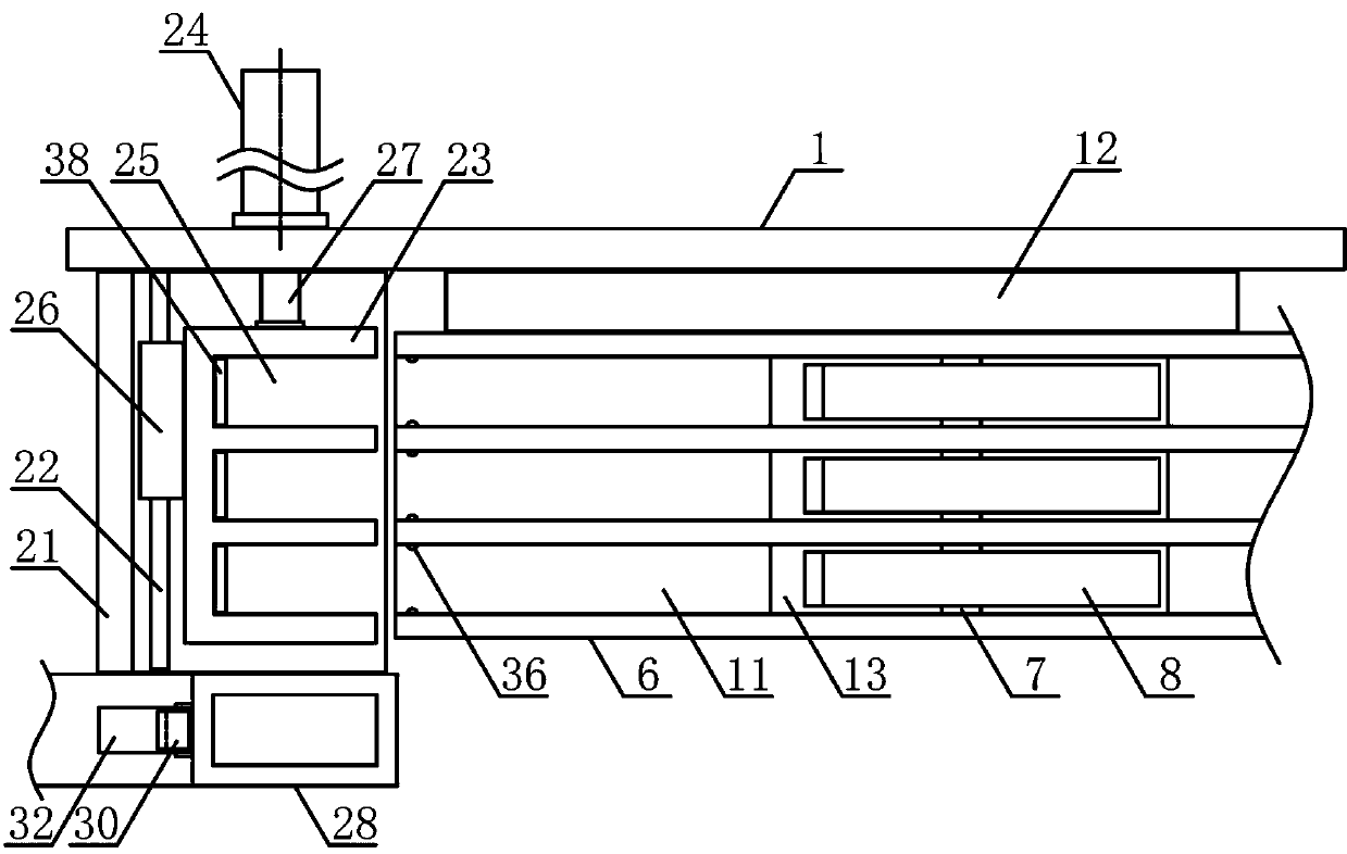
[0018] Such as figure 1 and figure 2 As shown, the present invention is a kind of material guide mechanism for ring-shaped workpieces, including material guide bracket 1, material transfer mechanism 2, pusher mechanism 3 and blanking mechanism 4, material transfer mechanism 2 and pusher mechanism 3 along the The inclination direction is fixedly arranged on one side of the material guide bracket 1 sequentially from top to bottom, and the blanking mechanism 4 is vertically fixedly arranged on the material guide bracket 1 on the side of the pushing mechanism 3 . Such as image 3 As shown, the material transfer m...


PUM


Abstract

The invention discloses a combined guiding mechanism for annular workpieces, and belongs to the field of workpiece transfer machining mechanical equipment. The mechanism is characterized in that the upper side of a conveying bracket is sequentially provided with a plurality of guiding chutes along the inclination direction, a guiding rotary shaft is sequentially, vertically and fixedly provided with a plurality of guiding rotary plates along the horizontal direction, and a pushing bracket is sequentially and uniformly provided with a plurality of bearing clamp grooves matched with the guidingchutes in sizes and specifications along the side of the conveying bracket; and a pushing piston rod of a horizontal pushing air cylinder output end is fixedly connected with the middle of one side ofthe pushing bracket, a guiding pipe is vertically and fixedly arranged on a guiding bracket on one side of a bearing bracket, and a baffler placing groove positioned on one side below the guiding pipe is internally provided with a falling baffler. The combined guiding mechanism for the annular workpieces has the advantages that structure design is reasonable, combined conveying of a plurality ofannular workpieces is achieved, and the annular workpieces can be unloaded and conveyed one by one, thus improving conveying and machining automation degree of the workpieces as well as meeting usingrequirements of machining.

Description

technical field [0001] The invention belongs to the field of workpiece conveying and processing machinery, and in particular relates to a combining and guiding mechanism for circular workpieces, which is mainly used for continuous combining and conveying of circular workpieces. Background technique [0002] The mechanical workpiece is a single piece that makes up the machine and its inseparability. It plays an important role in the automation industry. The mechanical workpiece includes the connection of parts, the supporting parts, the lubricating lubrication system and the sealing Components, components of the transmission system that transmits motion and energy, there are many types of workpieces, which can be mainly divided into: shaft sleeve workpieces, disc cover workpieces, fork bracket workpieces and box body workpieces according to the function and shape of the workpiece. The main part of the structure of the shaft sleeve workpiece is a coaxial rotary body, which mai...

Claims


Application Information

Patent Timeline
Patent Type & Authority Applications(China)
IPC IPC(8): B65G47/24B65G47/82
CPCB65G47/24B65G47/82B65G47/8815
Inventor 郭煜萍
Owner 滨州市沾化区蓝乔生物科技有限公司
Why Eureka
Try Eureka