
Erecting method for concrete pouring formwork with structural transition layer comprising H-type steel crossbeam

A technology of H-shaped steel and concrete, which is applied in the direction of construction, building structure, and construction material processing, etc., and can solve the problems of inability to turn around materials and materials, occupying labor, and insufficient construction space, etc.

Inactive Publication Date: 2014-10-22
SHANGHAI ERSHIYE CONSTR CO LTD +1
View PDF5 Cites 5 Cited by
  • Summary
  • Abstract
  • Description
  • Claims
  • Application Information

AI Technical Summary

Problems solved by technology

[0003] The purpose of the present invention is to improve the support of the traditional transfer floor beam slab formwork, the lower support system takes up a lot of materials and space for a long time, resulting in insufficient construction space, inability to turn around materials and materials, and taking up a lot of labor, which in turn leads to increased construction costs and extended construction periods And other issues

Method used


Image

  • Erecting method for concrete pouring formwork with structural transition layer comprising H-type steel crossbeam
  • Erecting method for concrete pouring formwork with structural transition layer comprising H-type steel crossbeam

Examples


Embodiment Construction

[0027] The present invention is further illustrated below by specific examples.

[0028] Take the construction of a transfer beam with a length of 1200×2500mm and a span of 8400mm as an example.

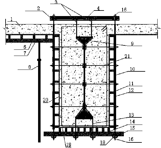
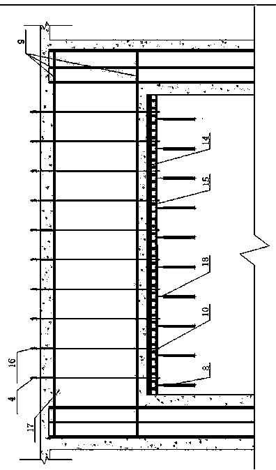
[0029] like figure 1 , figure 2 Shown:

[0030] In the first step, the adjustable scaffolding 8 is set up under the H-shaped steel beam 17 with a vertical pole spacing of 700mm, a horizontal vertical pole spacing of 512mm, 416mm, and 512mm, and a step distance of 1500mm;

[0031] In the second step, on the top of the adjustable scaffold 8, double steel pipes 18 with a diameter of 48mm and a wall thickness of 3.5mm are installed along the longitudinal direction of the H-shaped steel beam 17 as horizontal load-bearing members, a total of 4;

[0032] The third step is to install H-shaped steel beams 17 horizontal main keels 15 and horizontal secondary keels 14 on the double steel pipes 18 as required. The horizontal main keel 15 is made of 50×100mm wooden squares with a spacing of ...


PUM


Abstract

The invention relates to an erecting method for a concrete pouring formwork with a structural transition layer comprising an H-type steel crossbeam. The method includes erecting an adjustable scaffolding; mounting two steel pipes; mounting a main horizontal keel and an auxiliary horizontal keel; paving a bottom concrete pouring formwork; hanging the H-type steel crossbeam to a designed position; allowing a hanging rib to penetrate the bottom concrete pouring formwork to fasten with the two steel pipes; binding a reinforcement cage; mounting side main keels, side auxiliary keels and side concrete pouring formworks on two sides of the H-type steel crossbeam; mounting horizontal oppositely-pulling bolts; transversely mounting a U-steel above the H-type steel crossbeam and the floor top plate; mounting side hanging ribs, which are firmly connected to the U-steel and the H-type steel crossbeam, on two sides of the U-steel; separating the scaffolding from the formwork; pouring concrete; dismantling the formwork through a temporary scaffolding when the dismantling condition is met; dismantling the temporary scaffolding. The erecting method has the advantages that a simple and feasible scheme is provided for structural transition layer crossbeam construction on the premise of guaranteeing the anti-bending, anti-shearing and anti-disturbance performances.

Description

technical field [0001] The invention relates to the field of building engineering structure construction, in particular to a method for setting up a pouring formwork for a reinforced concrete girder at a structural transition between floors. Background technique [0002] When the structure form of the upper part and the lower part of the building is different, the structural conversion and load transfer are usually carried out through the transfer layer. Because the transfer floor usually has the characteristics of large cross-section, large span, and self-heavy, the formwork system of the steel concrete structure must be safe, reliable and of guaranteed quality. In the process of supporting the formwork of the transfer beam, if the conventional method of formwork is adopted, the girder scaffolding support system must continue to be erected to several floors below the transfer layer to meet the load requirements. In this way, a large amount of materials and space will be...

Claims


Application Information

Patent Timeline
IPC IPC(8): E04G21/02
Inventor 赵建立韩建岳齐贤
Owner SHANGHAI ERSHIYE CONSTR CO LTD
Learn More