Chain

A chain and sprocket technology, applied in the chain field, can solve the problems of increasing power loss between the sprocket and the chain 500, reducing the durability of the inner connecting piece plate 501, and reducing the power transmission performance of the chain 500, etc., achieving simple assembly and fewer parts. The effect of reducing and increasing strength

Active Publication Date: 2014-10-22
TSUBAKIMOTO CHAIN CO
View PDF7 Cites 0 Cited by
  • Summary
  • Abstract
  • Description
  • Claims
  • Application Information

AI Technical Summary

Problems solved by technology

[0012] When such mutual friction occurs, the inner surface 501a wears and causes the strength of the inner connector plate 501 to decrease, thereby reducing the durability of the inner connector plate 501 and thus reducing the durability of the chain 500, causing contact noise, and Due to the friction between the sprocket teeth 511 and the inner link plate 501, the power loss between the sprocket and the chain 500 increases, and there is a problem that the power transmission performance of the chain 500 decreases.

Method used


Image

  • Chain
  • Chain
  • Chain

Examples


Embodiment

[0044] Below, refer to Figure 1 ~ Figure 4 Examples of the present invention will be described.

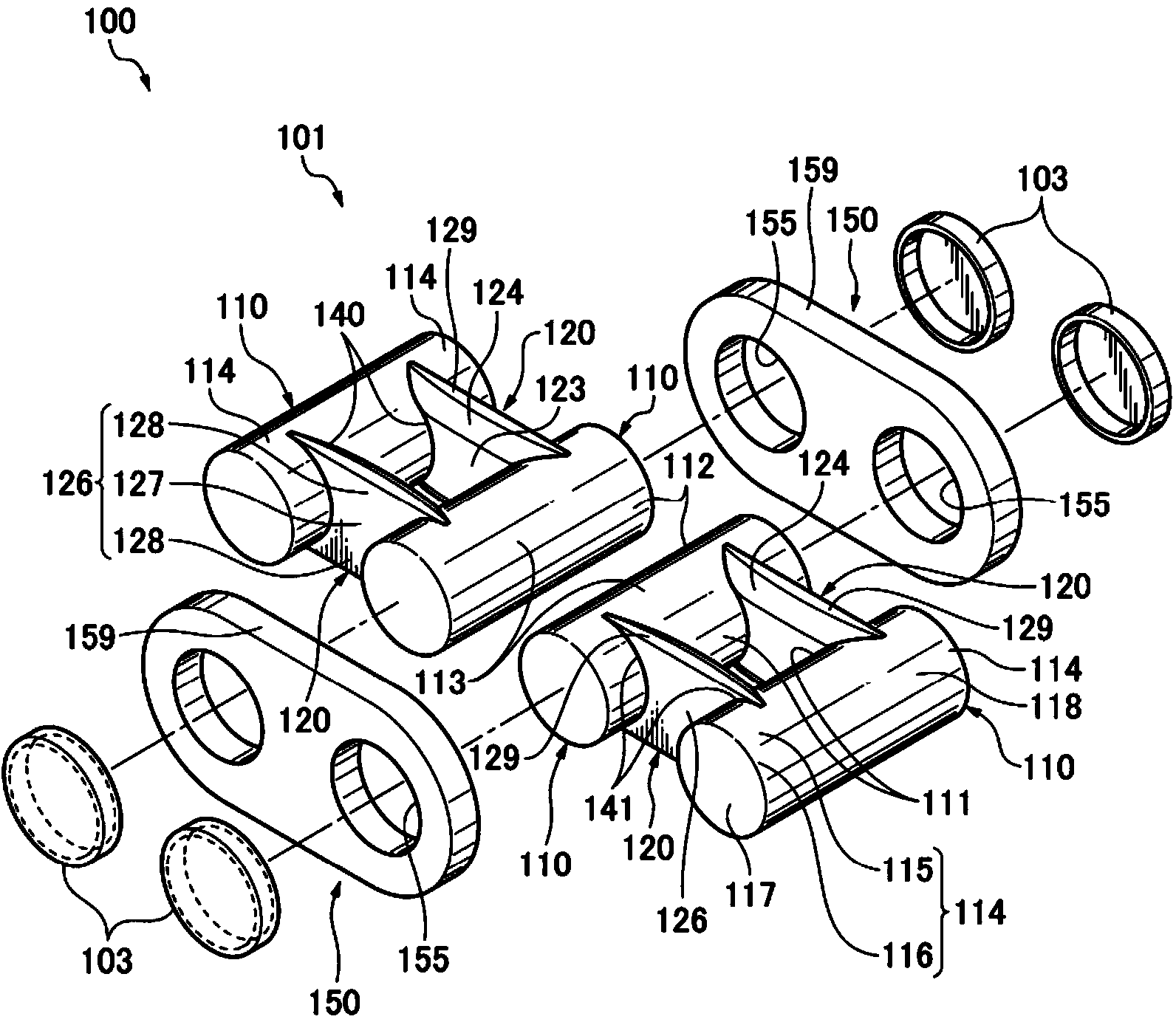
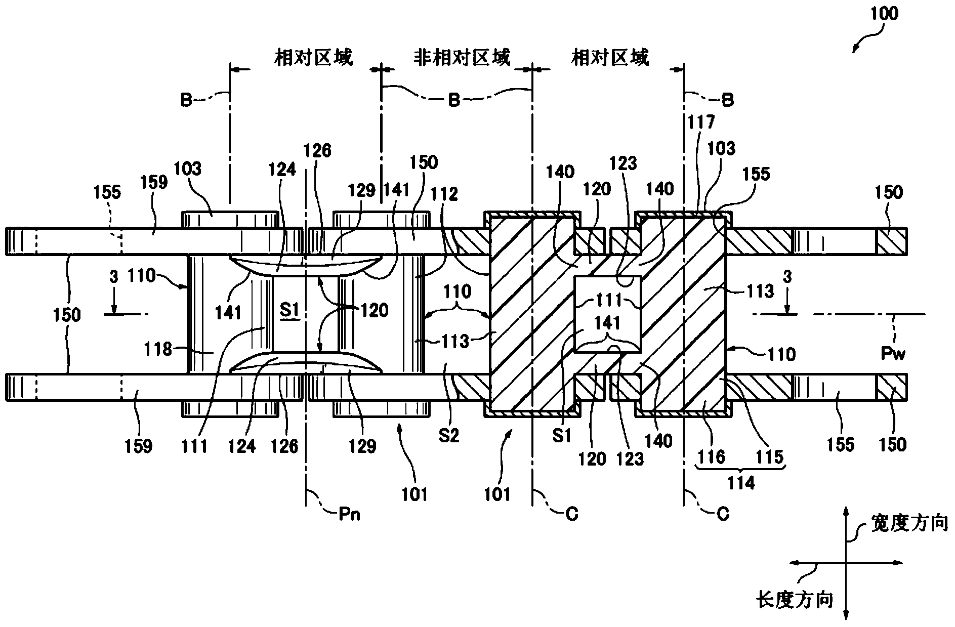
[0045] refer to Figure 1 ~ Figure 3 It can be seen that, in the embodiment of the present invention, the chain 100 as a transmission chain is a jointless chain, which is provided with: a plurality of connector units 101 constituting an inner connector; and a plurality of pairs of connectors constituting an outer connector. Plate 150, each connector unit 101 and pair of connector plates 150 of all connector units 101 and all groups of 1 pair of connector plates 150 pass through the connecting pin portion 110 of the connector unit 101 (hereinafter referred to as "pin"). The sections 110") alternate lengthwise and are flexibly connected about the curved centerline C of the pin section 110, thereby forming a jointless chain.

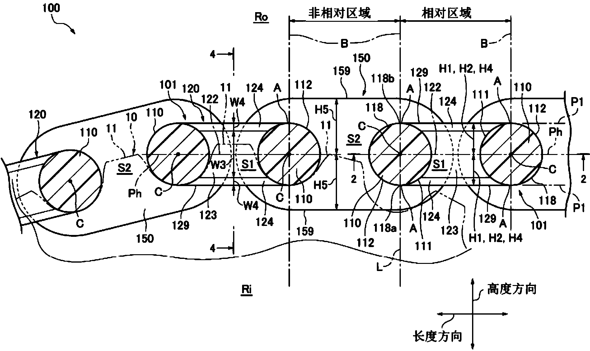
[0046] The chain 100 and the winding of the chain 100 have a plurality of sprockets 10 ( image 3 A sprocket mechanism (a part of one of the sprockets 10 i...


PUM


Abstract

The invention provides a chain which can improve chain intensity and improve endurance, quiet performance and power transmission performance of a flat portion through avoiding or restraining mutual friction between a chain wheel and the flat portion when the chain wheel and the chain are engaged. Concretely, the chain (100) can be flexibly connected to a connecting unit (101) of a pair of connecting piece flats (150) so that a pair of connecting pins (110) and a pair of flat portions (120) are connected. On an inner side surface of the flat portions (120) and on a side (Ri) of the chain wheel, a backward surface (124) is in a plane shape backward in a farther direction compared with a central intersecting portion (122) in a width direction relative to a width central panel (Pw).

Description

technical field [0001] The invention relates to a chain, which is formed by connecting a plurality of inner connectors and outer connectors alternately and flexibly in the length direction, and is wound on the sprocket. This chain is used, for example, as a transmission chain. Background technique [0002] Generally speaking, a chain wound on a sprocket is formed as follows, each of a plurality of inner connectors and a plurality of outer connectors are interactively and bendably connected by connecting pins loosely embedded in bushings in the length direction of the chain. An inner connecting piece and an outer connecting piece, the inner connecting piece is pressed into a pair of bushings on a pair of inner connecting piece flat plates, and the outer connecting piece is pressed into a pair of connecting pins on a pair of outer connecting piece flat plates. [0003] In addition, there is also known a chain in which a pair of inner link flat plates and a pair of bushes cons...

Claims


Application Information

Patent Timeline
Patent Type & Authority Applications(China)
IPC IPC(8): F16G13/06
CPCF16G13/06
Inventor 横山正则
Owner TSUBAKIMOTO CHAIN CO
Why Eureka
Try Eureka