Reflective Illumination Device Based on Laser Excited Phosphors

A lighting device and fluorescent powder technology, applied in the field of lighting, can solve problems such as inconvenient installation and maintenance, impracticability, poor lighting effect, etc., and achieve the effects of wide application environment, convenient maintenance and replacement, and increased lighting intensity

Inactive Publication Date: 2016-05-25
河北精锐电子科技有限公司
View PDF5 Cites 0 Cited by
  • Summary
  • Abstract
  • Description
  • Claims
  • Application Information

AI Technical Summary

Problems solved by technology

[0004] (1) Inconvenient installation and maintenance: Since the light-emitting part of the existing lighting device is set above the illuminated building, the lighting device is generally installed at a higher position, such as tunnel lighting and residential corridor lighting , are installed on the top of the tunnel and the top of the floor. When the lighting device is installed or the lighting device fails, the maintenance personnel need to use external force to touch the lighting device to carry out the corresponding installation, maintenance and replacement. For the lighting of the residential corridors, it may Maintenance is relatively simple, but it is quite difficult to install and maintain lighting devices in tunnels or public places such as parking lots;
[0005] (2) Poor lighting effect: Since tunnels and parking lot lighting places are relatively empty, from the perspective of cost, the lighting devices installed are limited, so the lighting effect often does not meet the requirements of customers, and if the lighting effect needs to be strengthened, It can only increase the lighting device, which increases the cost and cannot satisfy the requirements of both parties;
[0006] (3) The lighting cannot be adjusted: the existing lighting devices are directly fixed on the top of the building to be illuminated, the brightness and angle of the lighting cannot be adjusted, and the color is single, which cannot meet the lighting needs of various situations

Method used


Image

  • Reflective Illumination Device Based on Laser Excited Phosphors
  • Reflective Illumination Device Based on Laser Excited Phosphors
  • Reflective Illumination Device Based on Laser Excited Phosphors

Examples


Embodiment

[0034] Embodiment A reflective lighting device based on laser-excited phosphors

[0035] This embodiment is a reflective lighting device based on laser-excited phosphors, which includes:

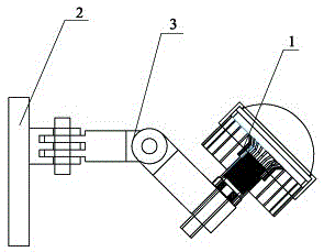
[0036] (1) An illuminating device having a laser, the illuminating device figure 1 , figure 2 shown, including:

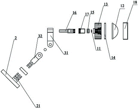
[0037] ①The laser light-emitting module 1 with adjustable light spot, the laser light-emitting module 1 in this embodiment is as follows figure 2 As shown, it includes a laser light source 11, an adjusting mechanism for adjusting the spot size of the light emitted by the laser light source 11, and a lens mechanism for transmitting light. The lens mechanism includes a transparent lens 12 and a heat sink 13 for dissipating heat for the laser light source 11 .

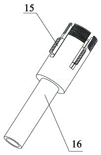
[0038] The adjustment mechanism such as image 3 , Figure 4 As shown, it includes a light source fixing seat 15 and a light source fixing seat movable bracket 16 , and the laser light source 11 is fixed on the light...


PUM


Abstract

The invention discloses a reflected illumination device based on laser light excitation of fluorescent powder. The reflected illumination device based on laser light excitation of the fluorescent powder comprises a reflector and an emitting device with a laser, the reflector coated with the fluorescent powder is capable of exciting autologous transition by light emitted by the laser so as to emit light different in color, an illumination device comprises a laser light-emitting module adjustable in light spot and a fixing base used for fixing the laser light-emitting module on a building, the laser light-emitting module is rotatably arranged on the fixing base through a middle support mechanism, and a reflecting surface of the reflector is opposite to a light-emitting end of the illumination device and does not contact with the illumination device. The reflected illumination device based on laser light excitation of the fluorescent powder has the advantages of simple structure, convenience in maintenance, capability of meeting illumination needs of different environments and applicability to any place requiring illumination.

Description

technical field [0001] The invention belongs to the field of lighting, and relates to a laser-excited phosphor powder lighting device, in particular to a laser-excited phosphor powder-based reflective lighting device. Background technique [0002] At present, lighting devices are widely used, whether it is corridor lighting in residents' daily life, parking lot, square lighting, or tunnel lighting in transportation, lighting devices are indispensable. With the continuous development of science and technology, lighting devices are also constantly improving. For example, the wide application of LED lamps is that because of their advantages of low power, low energy consumption, long life and high brightness, it basically replaces the traditional lighting methods. [0003] Although the lighting device has developed rapidly and has the above-mentioned advantages, the existing lighting device basically still relies on the light directly emitted by the light-emitting device for lig...

Claims


Application Information

Patent Timeline
Patent Type & Authority Patents(China)
IPC IPC(8): F21S8/00F21V14/02F21V7/22F21V21/30F21Y103/10F21Y115/10
Inventor 李达
Owner 河北精锐电子科技有限公司
Why Eureka
Try Eureka