
Large-scale missile engine six-component dynamometry and calibrating device

A technology for calibrating device and engine, applied in the direction of measuring device, force/torque/work measuring instrument calibration/test, measuring force component, etc., can solve the problem that there is no literature available for large-load six-component force measuring equipment, etc. Achieve the effect of saving development costs and maintenance costs, improving measurement accuracy, and high loading accuracy

Active Publication Date: 2014-10-22
CHINA ACAD OF AEROSPACE AERODYNAMICS
View PDF5 Cites 24 Cited by
  • Summary
  • Abstract
  • Description
  • Claims
  • Application Information

AI Technical Summary

Problems solved by technology

However, there is no literature available on large-load six-component force-measuring equipment that can be calibrated on-site

Method used


Image

  • Large-scale missile engine six-component dynamometry and calibrating device
  • Large-scale missile engine six-component dynamometry and calibrating device
  • Large-scale missile engine six-component dynamometry and calibrating device

Examples


Embodiment Construction

[0039] Below in conjunction with accompanying drawing, the present invention is described in detail, specifically as follows:

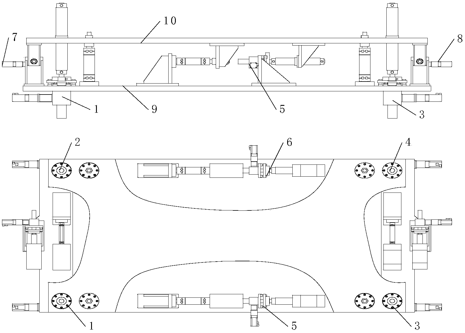
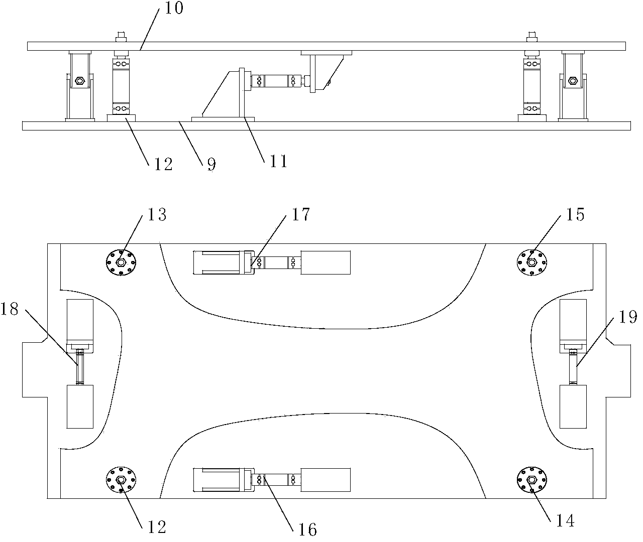
[0040] Such as figure 1 As shown, a six-component force measurement and calibration device for a large missile engine includes eight force generators 1-8, a fixed frame 9, a floating frame 10 and eight force transmission components 12-19; ​​when the device is used to measure force, the force generator does not work, figure 2 The structure when the force generator is installed is given, hereinafter referred to as the force measuring device.

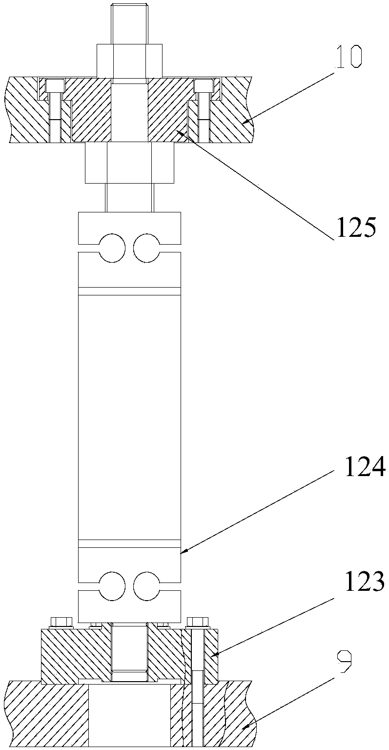
[0041] Among them, four force transmission components 12, 13, 14, 15 are vertically installed between the fixed frame 9 and the floating frame 10, and are arranged in a square shape; the other four force transmission components 16-19 are respectively fixed on the floating frame 10 through the upper and lower support frames. and on the fixed frame 9, and these four force transmission component axes 16-19 are ins...


PUM


Abstract

A large-scale missile engine six-component dynamometry and calibrating device. Four force transmission assemblies are vertically mounted between a fixed frame and a floating frame and are arranged in a square shape. The other four force transmission assemblies are respectively fixed to the floating frame and the fixed frame though upper and lower support frames. Axes of the four force transmission assemblies are installed horizontally relative to the floating frame, and the installation positions are parallel to four edges of the above square shape. Four force generators are vertically installed on the fixed frame and the floating frame, the other four force generators are respectively horizontally fixed between the floating frame and the fixed frame through the support frames, and the installation positions are respectively parallel to four edges of the above square shape. During calibration, force generated by the force generators is transferred to a working force sensor through the floating frame, and calibration is realized according to information measured by the working force sensor. During dynamometry, the force generators do not work, measured force is transferred to the working force sensor through the floating frame, and force and moment which need to be measured are obtained according to information measured by the working force sensor.

Description

technical field [0001] The invention is used for the free-jet force measurement test of a missile engine under high-altitude environment and high Mach number conditions, and belongs to the technical field of aviation test and test. Background technique [0002] Similar rocket free-jet test equipment in the United States, Russia, Japan and other countries has been in operation for many years. Most of the matched force measurement devices are single-component or three-component force measurement equipment. No equipment that simultaneously measures six-component force and moment has been found. The most representative is the NASA LANGLEY 8ft high-temperature wind tunnel in the United States, and its matching force-measuring equipment also has three longitudinal components, namely axial force, normal force and pitching moment. [0003] There are similar equipment used in the pre-research stage in China. The matching force-measuring equipment is small in size and has a small load...

Claims


Application Information

Patent Timeline
Patent Type & Authority Applications(China)
IPC IPC(8): G01L5/16G01L25/00
Inventor 郑芳刘丹孙侃皮组成郎卫东武家陶
Owner CHINA ACAD OF AEROSPACE AERODYNAMICS
Learn More