Motor and manufacturing method thereof

A manufacturing method and magnetic steel technology, applied in the manufacture of stator/rotor body, magnetic circuit shape/style/structure, magnetic circuit rotating parts, etc., can solve the problem of permanent magnet motor magnet demagnetization, affecting motor performance and life, without Set anti-demagnetization structure and other issues to achieve the effect of improved anti-demagnetization ability, long life and improved anti-demagnetization ability

Inactive Publication Date: 2014-10-22
MIDEA WELLING MOTOR TECH SHANGHAI
View PDF6 Cites 4 Cited by
  • Summary
  • Abstract
  • Description
  • Claims
  • Application Information

AI Technical Summary

Problems solved by technology

[0004] The motor in the prior art, as shown in Figure 1(a) to Figure 1(d), has its magnetic steel 2a attached to the outside of the rotor core 1a, for example, the patent number: ZL201220308590.0, which provides a motor Among them, the magnetic steel is fixed on the rotor core, and there is no anti-demagnetization structure. When the motor is under high temperature conditions and inputs a large current (outputs a large torque), the demagnetization phenomenon of the permanent magnet motor magnetic steel is serious, which affects the performance and life of the motor.

Method used


Image

  • Motor and manufacturing method thereof
  • Motor and manufacturing method thereof
  • Motor and manufacturing method thereof

Examples


Embodiment 2

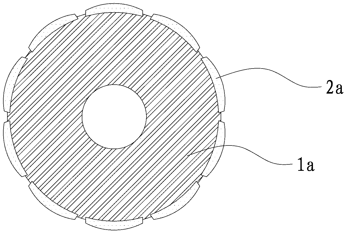
[0041] Different from the slot in the motor provided in Embodiment 1, in this embodiment, as shown in FIG. 3( a ) and FIG. 3( b ), the end of the magnetic steel 2 extends into the slot 101 . The width of the slot 101' on the rotor core 1' of the rotor 10' can be greater than the gap between the adjacent magnets 2', and the opening of the slot 101' has a larger width, so that the slot 101' extends to the gap between the magnets 2'. The bottom part further weakens the strength of the magnetic field formed by the armature reaction at the corners at both ends of the magnetic steel 2', and more effectively avoids demagnetization of the magnetic steel 2'.

Embodiment 3

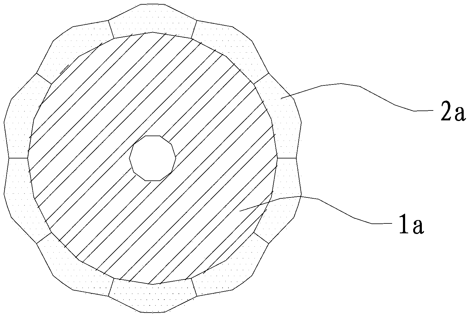
[0043] Different from the shape of the non-magnetic insulator in the motor provided in Embodiments 1 and 2, in this embodiment, such as Figure 4 As shown, the slot on the rotor core 1'' of the rotor 10'' is provided with a non-magnetic insulator 3'', and both sides of the upper end of the non-magnetic insulator 3'' are provided with buckles on the magnetic steel 2' The raised portion 31'' at the upper end, the cross-section of the non-magnetic insulator 3'' is roughly in the shape of a "T", which is beneficial to improve the structural reliability of the magnetic steel 2''. In specific applications, the shape of the non-magnetic insulator 3'' can be set according to actual conditions.


PUM


Abstract

The invention is suitable for the technical field of motors, and discloses a motor and a manufacturing method thereof. The aforementioned motor comprises a rotor which comprises a rotor iron core and magnetic steel. There are multiple sets of magnetic steel arranged at the external side of the rotor iron core. The rotor iron core is provided with groove positions which are inwardly recessed from the external surface of the rotor iron core to a rotor. The groove positions are arranged between adjacent magnetic steel. The bottom part of the groove positions is closer to the center of the rotor in a way of being relative to the bottom surface of magnetic steel. The aforementioned manufacturing method comprises the following steps that a stator and the rotor iron core with the groove positions arranged at the external side surface are prepared; positioning strips are arranged in the groove positions; and magnetic steel is adhered at the external side of the rotor iron core, and the side surface of magnetic steel and the side surface of the positioning strips are enabled to be adhered. According to the motor and the manufacturing method thereof, the groove positions are arranged on the rotor iron core, and relatively high magnetic resistance is generated at the groove positions so that resistance to demagnetization of magnetic steel can be substantially enhanced when high current is inputted to the motor at high temperature. Besides, the motor is great in performance and long in the service life.

Description

technical field [0001] The invention belongs to the technical field of motors, and in particular relates to a motor and a manufacturing method thereof. Background technique [0002] At present, permanent magnet motors are divided into two types: magnetic steel label type and magnetic steel built-in type. For the magnetic steel label type permanent magnet motor, it has good control performance due to its own characteristics, and is widely used in industrial control, Various industries of medical machinery and pharmaceutical machinery have put forward various requirements for this kind of permanent magnet motor due to different industries. Among them, as far as the motor itself is concerned, the important index is the power density of the motor (the same volume output size ), wide working range (motor maximum operating speed and output torque), etc. [0003] In the current trend, the size of the motor is getting smaller and smaller, but the output torque of the motor is requi...

Claims


Application Information

Patent Timeline
Patent Type & Authority Applications(China)
IPC IPC(8): H02K1/27H02K15/03
Inventor 彭光明王飞陈金涛诸自强
Owner MIDEA WELLING MOTOR TECH SHANGHAI
Why Eureka
Try Eureka