
A protective casing for a treatment machine

A technology of a treatment machine and a shell, applied in the field of treatment instruments, can solve the problems that the treatment machine cannot be stopped immediately, interfere with the judgment of the treatment personnel, and the switch button fails, so as to reduce the incidence of medical accidents, ensure the control function and flexibility, The effect of avoiding impact loss

Active Publication Date: 2016-09-14
CHENGDU TRINIDAD ELECTRONICS EQUIP
View PDF4 Cites 0 Cited by
  • Summary
  • Abstract
  • Description
  • Claims
  • Application Information

AI Technical Summary

Problems solved by technology

[0003] At present, ion therapy devices on the market have a wide range of functions, but during medical treatment, the switch of the ion therapy device is exposed to the outside, and dust or water vapor from the outside can easily enter the electronic circuit inside the therapy device. At the time of innovation, the switch button directly failed, so that the treatment machine could not be stopped immediately after the operation was completed, and it interfered with the judgment of the treatment personnel, resulting in medical accidents

Method used


Image

  • A protective casing for a treatment machine

Examples


Embodiment 1

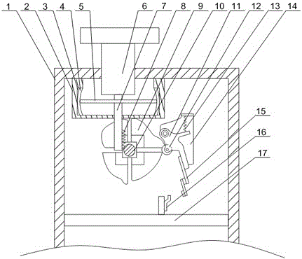
[0019] Such as figure 1 As shown, this embodiment includes a switch key 6 and a protective casing 1 with a through hole. The protective casing 1 is provided with a cylindrical sealing cavity 2, and an annular groove is formed on the inner wall of the sealing cavity 2. 3. The sealing gasket 4 is fixed in the annular groove 3, the switch key 6 is placed in the sealed cavity 2 through the through hole, and the bottom of the switch key 6 is connected with a movable rod 7 which runs through the bottom of the sealed cavity 2, and the movable rod 7 is fixed with a circular bottom plate 5, the outer circumference of the circular bottom plate 5 is always in contact with the gasket 4; it also includes a cam block 9 and a fixed block 14, the fixed block 14 is installed on the inner wall of the protective housing 1, and the cam block 9 is rotated The shaft 10 is rotated and installed on the protective shell 1, and the outer wall of the rotating shaft 10 is provided with a coarse thread, a...

Embodiment 2

[0022] Such as figure 1 As shown, in this embodiment, on the basis of Embodiment 1, the bottom of the switch key 6 is provided with a threaded hole, and the upper end of the movable rod 7 is screwed to the switch key 6 through the threaded hole. In the process of using for a long time, it is inevitable that there will be dust entering the open cavity through the through hole. The switch key 6 is threadedly connected with the movable rod 7, and the switch key 6 can be disassembled to facilitate manual cleaning of the sealed cavity 2. The cleanliness in the sealed cavity 2 is guaranteed.

[0023] When the switch key 6 is pressed down, the cam block 9 is separated from the roller 12, and the contact point swings freely under the action of the contact bracket's own gravity until it collides with the contact piece 16. At this time, it is located between the fixed block 14 and the contact point. The torsion spring 13 between them is stretched, and according to the active force and ...


PUM


Abstract

The invention discloses a protective shell of a therapeutic instrument. The protective shell comprises an on-off key and a protective shell body with a through hole. A cylindrical sealed cavity is formed in the protective shell body, the inner wall of the sealed cavity is provided with an annular groove, a sealing gasket is fixed into the annular groove, and the on-off key penetrates through the through hole and is arranged in the sealed cavity. The bottom of the on-off key is connected with a movable rod with one end penetrating through the bottom of the sealed cavity, and a circular base plate is fixed to the movable rod. The outer circumference of the circular base plate is in contact with the sealing gasket consistently. The sealing gasket can deform in the annular groove so that the circular base plate can be in contact with the sealing gasket in the sealed cavity consistently, complete sealing between the outside and the inside of the protective shell body is ensured, outside moisture or dust is completely prevented from entering the therapeutic instrument through the on-off key, the control function and the flexibility of switching-on and switching-off of the therapeutic instrument before and after the therapeutic instrument is used are ensured, the using efficiency of the therapeutic instrument is improved, and meanwhile the medical accident occurrence rate caused by the failure of switching-on and switching-off is reduced.

Description

technical field [0001] The invention relates to a therapeutic apparatus, in particular to a protective shell of a therapeutic apparatus. Background technique [0002] During the treatment of the ion therapy machine, according to different lesions, the treatment needles with different diameters are selected to contact or insert into the human lesions, and the gas molecules are separated by using the extremely high electric field strength formed in the tiny air gap between the contacts and the tissue to generate plasma. body flame. When a strong output is selected, a high temperature of about 3000°C is generated instantaneously, making the diseased tissue gasify and disappear. At the same time, because there is a thin coagulation layer under the gasification layer, it can prevent bleeding, protect the surface tissue, and make the wound heal quickly. When the weak output is selected, the lesion tissue can be coagulated or charred and necrotic, so as to achieve the purpose of ...

Claims


Application Information

Patent Timeline
Patent Type & Authority Patents(China)
IPC IPC(8): A61B18/12
Inventor 张文
Owner CHENGDU TRINIDAD ELECTRONICS EQUIP
Learn More