Adjustable annular jet pump

An annular jet and fluid tube technology, applied in the field of jet pumps, can solve the problems of reduced pressure ratio and boosting capacity, inability of the annular jet pump to operate, unable to meet working requirements, etc. simple effect

Inactive Publication Date: 2013-08-07
WUHAN UNIV
View PDF5 Cites 19 Cited by
  • Summary
  • Abstract
  • Description
  • Claims
  • Application Information

AI Technical Summary

Problems solved by technology

As the flow ratio between the sucked fluid and the working fluid increases, its pressure ratio and boosting capacity decrease
However, in actual operation, the external conditions change a lot, and the annular jet pump with a fixed area ratio often cannot operate in a better working range, and sometimes even cannot meet the working requirements, and replacing a new pump will consume a lot of material and financial resources and affect the entire system. system operation

Method used


Image

  • Adjustable annular jet pump
  • Adjustable annular jet pump
  • Adjustable annular jet pump

Examples


Embodiment 1

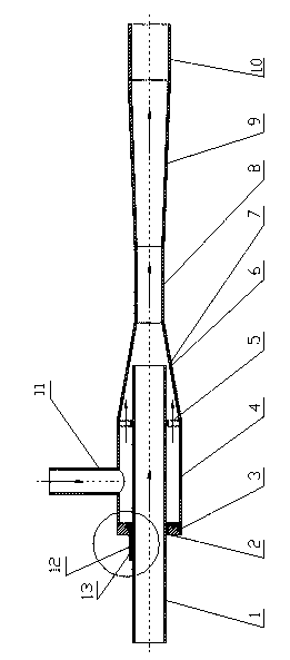
[0020] Below in conjunction with accompanying drawing, the present invention is further described: as figure 1 , figure 2 , Figure 4 As shown, an adjustable annular jet pump includes a rectification assembly, a mixing pipe 7, a throat pipe 8, a diffuser pipe 9, and an outlet pipe 10 connected in sequence. The rectification assembly includes a rectification pipe 4, a suction fluid pipe 1 and a working fluid Tube 11, the rectifying tube 4 communicates with the working fluid tube 11, and one end of the rectifying tube 4 is provided with an end cover 3, and the suctioned fluid tube 1 passes through the end cover 3 and can move axially relative to the end cover 3. A scale 12 is provided on the outer end of the end cap 3 , and a pointer 13 is provided on the pipe 1 for the sucked fluid. The end of the suctioned fluid pipe 1 and the mixing pipe 7 form a working nozzle 6 . According to the different scales on the scale corresponding to the pointer, the position of the suctioned f...

Embodiment 2

[0026] Such as figure 1 , image 3 , Figure 4 As shown, an adjustable annular jet pump includes a rectification assembly, a mixing pipe 7, a throat pipe 8, a diffuser pipe 9, and an outlet pipe 10 connected in sequence. The rectification assembly includes a rectification pipe 4, a suction fluid pipe 1 and a working fluid Tube 11, the rectifying tube 4 communicates with the working fluid tube 11, and one end of the rectifying tube 4 is provided with an end cover 3, and the suctioned fluid tube 1 passes through the end cover 3 and can move axially relative to the end cover 3. A scale 12 is provided on the outer end of the end cap 3 , and a pointer 13 is provided on the pipe 1 for the sucked fluid. The end of the suctioned fluid pipe 1 and the mixing pipe 7 form a working nozzle 6 . According to the different scales on the scale corresponding to the pointer, the position of the suctioned fluid channel and the flow area of ​​the nozzle can be determined, so as to determine the...


PUM


Abstract

An adjustable annular jet pump comprises a rectifying assembly, a mixing pipe (7), a throat pipe (8), a diffusing pipe (9) and an outlet pipe (10) which are sequentially connected. The rectifying assembly comprises a rectifying pipe (4), an absorbed fluid pipe (1) and a working fluid pipe (11); the rectifying pipe (4) is communicated with the working fluid pipe (11); one end of the rectifying pipe (4) is provided with an end cover (3); the absorbed fluid pipe (1) which penetrates through the end cover (3) can perform axial movement relative to the end cover (3); the outer end of the end cover (3) is provided with a scale (12); and the absorbed fluid pipe (1) is provided with a pointer (13). The adjustable annular jet pump has the advantages of being adjustable in area ratio and enabling the performance to be adjusted according to the working condition; being capable of achieving that an absorbed fluid channel smoothly and stably moves along an axis and simultaneously guaranteeing sealing for high pressure working fluids by increasing the existing mature transmission devices on the market; and being simple to operate namely that manual control can be performed and full-automatic control can also be achieved according to a scheduled program, simple in structure, low in cost and beneficial to promotion and application due to high cost performance.

Description

technical field [0001] The invention relates to a jet pump, in particular to an adjustable annular jet pump. Background technique [0002] The jet pump is a kind of fluid machinery and mixed reaction equipment that uses the shearing and turbulent diffusion of the jet to transfer mass and energy. The device has simple structure, reliable operation, low operation and maintenance costs, and is especially suitable for underwater, radiation, flammable and explosive occasions. [0003] According to the different nozzle structures used, jet pumps can be divided into two types: central jet pumps and annular jet pumps. The nozzle of the central jet pump is placed in the middle of the suction chamber, and the fluid to be sucked surrounds the outer end of the nozzle; the annular jet pump uses a ring nozzle, and the fluid to be sucked passes through the inner ring of the nozzle. In the annular jet pump, since the suction channel is in the middle and parallel to the throat, it is very ...

Claims


Application Information

Patent Timeline
Patent Type & Authority Applications(China)
IPC IPC(8): F04F5/46F04F5/00
Inventor 龙新平杨雪龙康勇王晓川杨晓峰
Owner WUHAN UNIV
Why Eureka
Try Eureka