Deep well rescuing device

A rescuer and deep well technology, applied in the field of deep well rescuers, can solve the problems of danger, time-consuming and low efficiency of rescuers, and achieve the effects of high reliability and convenient disassembly and assembly.

Inactive Publication Date: 2014-10-29
BEIHANG UNIV
9 Cites 15 Cited by

AI-Extracted Technical Summary

Problems solved by technology

At present, simple ropes are usually used to put rescuers into the underground for rescue. This re...

Method used

As shown in Figure 4 and Figure 5, the positioning mechanism is an umbrella-shaped support mechanism, which is used to locate the deep well rescue device on the well wall in the underground rescue process, so as to prevent the deep well rescue device from shaking in the well and reduce the rescue time. difficulty. Positioning mechanism comprises a motor 7, a leading screw 39 of about 180mm in length, an umbrella shaft 34 of about 170mm in length, axle sleeve 38 and umbrella telescoping mechanism. The umbrella telescoping mechanism consists of three connecting rods 37 of about 100mm in length, three umbrella poles 40 of about 100mm in length, six umbrella ribs 36 of about 110mm in length, two umbrella rib connectors 35, an umbrella pole connector 41, six 42 wheels. The rib connectors 35 are cylindrical parts, and the two ends of each rib connector are provided with pin holes whose axes are perpendicular to each other. Each umbrella rib connector is connected with three ribs 36 to form two sets of ribs through three groups of lugs extending radially from its outer wall and forming an angle of 120 degrees. There are threads on the top of the umbrella shaft, and two groups of pin holes corresponding to the pin holes of the rib connector 35 are respectively provided with two sets of pin holes perpendicular to each other at about 20 mm from both ends of the umbrella shaft, so that each rib connector is connected with a pin. Be fixed on the umbrella axis 34. A wheel 42 is installed at the end of each umbrella rib 36 , the upper and lower ribs are conne...

Abstract

The invention provides a deep well rescuing device which is used for rescuing persons trapped in a deep well. The deep well rescuing device comprises a bearing structure, a positioning mechanism, a clamping mechanism, a position adjustment mechanism, a lifting mechanism, a master control system and a communication device, wherein the bearing mechanism comprises a plurality of support plates and a plurality of support shafts, and all the support plates and the support shafts form the multi-layer bearing structure; the positioning mechanism is used for positioning the deep well rescuing device to a well wall so as to prevent the deep well rescuing device from swinging; the clamping mechanism is used for enabling a mechanical arm to rotate by small angles in a pivoted mode in the radial direction in the rescuing process so as to fasten the trapped person in the deep well rescuing device; the position adjustment mechanism is used for adjusting the mechanical arm to an appropriate position in the circumferential direction so as to stretch the mechanical arm into the well; the lifting mechanism is used for making direct contact with the human body and protecting the person in the deep well rescuing device.

Application Domain

Technology Topic

Image

  • Deep well rescuing device
  • Deep well rescuing device
  • Deep well rescuing device

Examples

  • Experimental program(1)

Example Embodiment

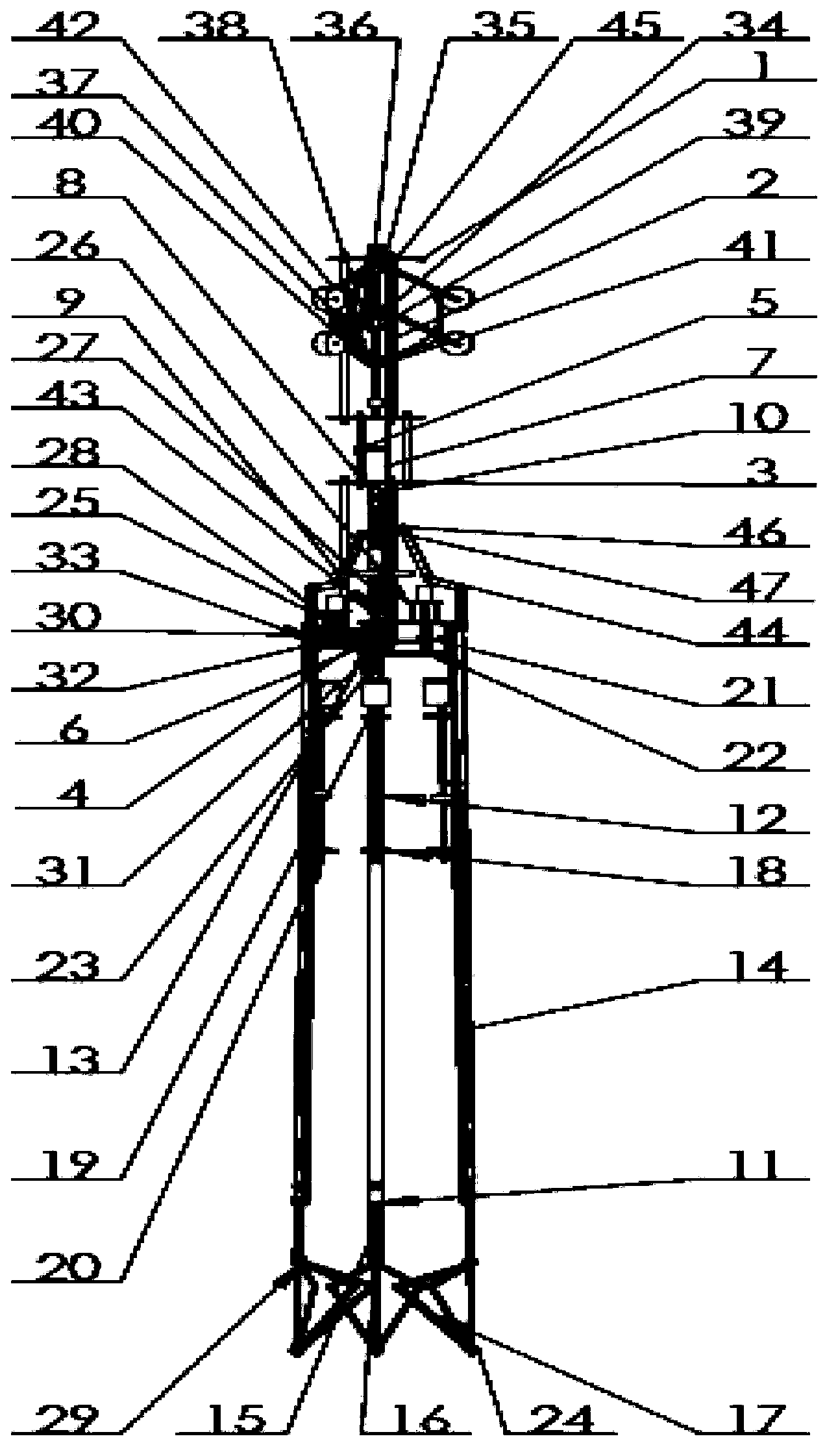
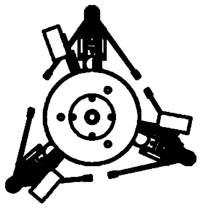
[0024] figure 1 is the front view of the deep well rescue device according to the present invention, figure 2 It is a top view of the deep well rescue device according to the present invention. As shown in the figure, the deep well rescue device includes a supporting structure, a positioning mechanism, a clamping mechanism, a positioning mechanism, a lifting mechanism, a master control system and a communication device. By closing the mechanical arm and stretching it under the trapped person and then opening it, the trapped person is embraced in the rescue device, and finally the rescue device and the trapped person are pulled up together with a rope, thereby realizing underground rescue.
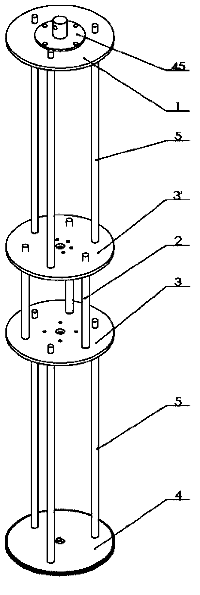
[0025] like image 3 As shown in , the support structure is a layered structure, including four support plates, the upper plate 1, the lower middle plate 3, the upper middle plate 3' and the lower plate 4, and the four support plates are all circular plates with a diameter of about 150mm , each support plate has installation holes evenly distributed in the circumferential direction, and the installation holes are through holes. The support structure also includes six support shafts 2 with a length of about 380 mm and three support shafts 5 with a length of about 140 mm, and threads are provided at both ends of each support shaft. The upper plate 1 and the upper middle plate 3' are connected by three support shafts 2 with a length of about 380 mm at an angle of 120 degrees to each other, and the upper middle plate 3' and the lower middle plate 3 are connected by three support shafts 5 with a length of 140 mm at an angle of 120 degrees to each other Connection, the lower middle plate 3 and the lower plate 4 are connected by three support shafts 2 with a length of 380 mm at an angle of 120 degrees to each other, forming a layered support structure. The support shafts are connected to the plates in such a manner that the ends of the support shafts are passed through mounting holes of the plates, and then the support shafts are connected to the plates with nuts. Each supporting plate also includes a central hole, and the upper plate, the upper middle plate and the lower middle plate also include a plurality of small holes evenly distributed in the circumferential direction near the central hole, and the number of small holes is preferably four or six. The central hole and the small hole are through holes for bolt connection. Specifically, the upper plate 1 is connected with the positioning mechanism and the rope fixing ring 45 through bolts, the lower middle plate 3 is connected with the motor 7 through bolts, the lower plate 4 has transmission teeth, and the transmission teeth mesh with the pinion shaft in the positioning mechanism. Gear drive for positioning mechanism.
[0026] like Figure 4 and Figure 5 As shown, the positioning mechanism is an umbrella-shaped support mechanism, which is used to position the deep well rescue device on the well wall during the underground rescue process, so as to prevent the deep well rescue device from shaking underground and reduce the difficulty of rescue. Positioning mechanism comprises a motor 7, a leading screw 39 of about 180mm in length, an umbrella shaft 34 of about 170mm in length, axle sleeve 38 and umbrella telescoping mechanism. The umbrella telescoping mechanism consists of three connecting rods 37 of about 100mm in length, three umbrella poles 40 of about 100mm in length, six umbrella ribs 36 of about 110mm in length, two umbrella rib connectors 35, an umbrella pole connector 41, six 42 wheels. The rib connectors 35 are cylindrical parts, and the two ends of each rib connector are provided with pin holes whose axes are perpendicular to each other. Each umbrella rib connector is connected with three ribs 36 to form two sets of ribs through three groups of lugs extending radially from its outer wall and forming an angle of 120 degrees. There are threads on the top of the umbrella shaft, and two groups of pin holes corresponding to the pin holes of the rib connector 35 are respectively provided with two sets of pin holes perpendicular to each other at about 20 mm from both ends of the umbrella shaft, so that each rib connector is connected with a pin. Be fixed on the umbrella axis 34. A wheel 42 is installed at the end of each umbrella rib 36 , the upper and lower ribs are connected by a connecting rod 37 , and the lower group of ribs is connected with an umbrella pole connector 41 through an umbrella pole 40 . The umbrella pole connector 41 is a cylindrical part, which is connected with the umbrella pole 40 through three sets of lugs protruding from its outer wall at 120 degrees. connect. The upper end of leading screw 39 and the lower end of umbrella axis 34 stretch into axle sleeve 38 from axle sleeve 38 two ends respectively, and the upper end of umbrella axis 34 is connected with the upper plate 1 of supporting structure by screw thread. The shaft sleeve 38 is fixedly connected with the umbrella shaft 34 through the pin hole on it, the upper end of the lead screw 39 is axially positioned through the shaft sleeve 38, and the lower end is connected with the motor 7 through the shaft coupling 10, 28, and the motor 7 is fixed on the supporting structure on the upper middle plate 3'. A nut is engaged on the lead screw 39, and the umbrella pole connecting piece is engaged on the nut. During work, the screw 39 is driven by the motor 7 to rotate, and the nut moves up and down with the rotation of the screw, thereby driving the umbrella pole connecting piece 41 to lift up and down to complete the retractable function of the umbrella mechanism. When the umbrella mechanism contracts (eg Figure 4 shown), the deep well rescue device can enter from the wellhead without hindrance, when the umbrella mechanism is deployed (such as Figure 5 shown), the deep well rescuer can be positioned on the well wall.
[0027] like Image 6 As shown, the clamping mechanism is a screw drive mechanism, which is used to make the mechanical arm pivot at a small radial angle during the rescue process, so as to achieve the purpose of fastening the person in the deep well rescuer. The clamping mechanism is wrapped with a ball screw 8 about 300mm long, a push plate, three springs 47, a motor, and three sets of drive rod assemblies with a length of about 100mm, and each set of drive rod assemblies includes three connecting rods 43, 44 , 46. A nut 9 is engaged on the lead screw 8, and the push plate is engaged on the nut through its central hole. One end of each spring is connected to the part fixedly sleeved on the lead screw, and the other end is connected to a transmission rod assembly. The upper end of the leading screw 8 is connected to the motor fixed on the lower middle plate 3 through a shaft coupling, and the lower end is connected with the central shaft 6 of the lower plate 4 . When working, the motor 7 drives the lead screw to rotate, and the nut moves up and down with the rotation of the lead screw, thereby driving the push plate to lift up and down. The lift of the push plate causes the transmission rod assembly to pivot at a small radial angle, and then after being driven by the drive rod Drive the lifting mechanism to rotate inward or outward in the radial direction to complete the clamping function.
[0028] like Figure 7 As shown, the position adjustment mechanism is a set of gear transmission mechanism, which is used to adjust the mechanical arm to a suitable position in the circumferential direction so as to extend the mechanical arm into the well. The positioning mechanism includes three pinion shafts 21, 30 and 32 engaged with the transmission teeth of the lower plate 4 of the supporting structure, and each pinion shaft is installed between the upper connecting plate 23 and the lower connecting plate 23' respectively, and the upper connecting plate One end of the plate 23 and the lower connecting plate 23' is respectively provided with mounting holes to be fixed on the central axis 6 of the lower plate 4, and the other ends are connected to each other by connecting pieces 22, 31, 33, and the connecting pieces 22, 31, 33 are connected to the upper and lower sides. The plates 23, 23' are preferably interconnected by bolt-nut assemblies. The connectors 22, 31, 33 are directly connected to the mechanical arm. Each upper connecting plate 23 is provided with motor bases 25 and 26, and each motor base 25 and 26 is respectively fixed with a motor 27. During work, the three pinion shafts 21, 30 and 32 are driven to rotate by the three motors 27, so that the position adjustment mechanism rotates along the transmission teeth to achieve the purpose of adjusting the circumferential position of the mechanical arm.
[0029] like Figure 8 and Figure 9 As shown, the lifting mechanism is a connecting rod telescopic mechanism, which is used to directly contact the human body and protect the person in the deep well rescue device. The lifting mechanism includes three T-shaped beams 11 with a length of about 1500mm, and one end of each T-shaped beam is connected with the positioning mechanism through a connecting piece 12, and the connecting piece 12 can be a screw or a pin. A motor base 18 is fixedly installed at about 100 mm below the position adjustment mechanism on each T-shaped beam 11, one end of the output shaft of the motor is installed on the motor base, and the other end is installed on the bearing 20, and the output shaft of the motor is manufactured Become leading screw 19. A nut is engaged on the leading screw 19, and a slide block 12 is fixed on the nut, and the slide block 12 is sleeved on the T-shaped beam through a through hole thereon. During work, the rotation of the leading screw 19 causes the nut to move up and down along the leading screw 19, so that the slide block moves up and down with the T-shaped beam as the guide rail. A transmission rod assembly is connected to the slide block, and the transmission rod assembly may include two push rods 14 . The push rod 14 is connected with the mechanical claw at the beam tail 15 by a pin, so that the up and down movement of the slider makes the push rod push the mechanical claw at the beam tail 15. Each mechanical claw includes three sets of support rods 16, 17, each set of support rods is composed of two connecting rods with a length of about 120mm, and the connecting rods are connected by fixing parts 24, 29, and the fixing parts may be pins. The mechanical claw has a structure that can be expanded or contracted, and it expands or contracts as the slider moves up and down during work. When it is in a suitable position below the person, it becomes the unfolded state, thereby enclosing the trapped person in the lifting mechanism. Preferably, the lifting mechanism can also be provided with soft materials, such as rubber pads, sponge pads and the like.
[0030] The master control system is a set of motor drive system controlled by computer, which is used to control the movement of the mechanism in real time. It includes computer, microcontroller, six motor driver boards and some wires. Rescuers on the ground control the operation of the motor by operating the computer to drive the movement of the rescuer to implement rescue.
[0031] The communication device includes a lighting system, a camera and a communication system, and circuit boards corresponding to the lighting system, the imaging system and the communication system are connected to a computer to obtain information about people trapped underground.
[0032] The working process of the deep well rescue device of the present invention will be described below.
[0033] Tie the rope on the rope fixing ring 45, hang it vertically from the ground into the well, monitor the camera, make the rescuer stop above the trapped person, drive the motor 7 of the positioning mechanism, drive the lead screw 39 to rotate, and the positioning mechanism launches, so that The wheels 42 contact the well wall and do not shake down the well, and the device completes the positioning. The rescuers on the ground observed the posture of the trapped person in the well through the camera, looking for three gaps of about 20mm. After finding a suitable gap, drive the motor 27 of the positioning mechanism to make the positioning mechanism work, and the positioning mechanism adjusts the circumferential positions of the three groups of mechanical arms so that the three groups of mechanical arms are aligned with the gaps found. After the position is adjusted, the rope is slowly lowered, and the rescuer moves down slowly along the well wall, so that each mechanical arm extends under the trapped person, and the mechanical claws of the lifting mechanism are in a contracted state at this time. When the mechanical arm stretched into the position that the fixing part 29 arrived below the trapped person, the leading screw 19 of the lifting mechanism was driven to rotate, so as to push the support rod 17 through the downward movement of the push rod 14 until the upper part of the support rod 17 was close to the level position, so that the mechanical rotation of the lifting mechanism is in the unfolded state, and the trapped person is surrounded by the mechanical claws of the lifting mechanism. Then, the screw 8 that drives the clamping mechanism rotates, and the connecting rods 43, 44, 46 are pushed by the push plate 9 so that the clamping mechanism pivots in the radial direction to clamp the trapped person. Finally, the motor 7 that drives the positioning mechanism puts up the positioning mechanism, and the people and the deep well rescuer are pulled out of the well by the rope, and the rescue task is completed.
[0034] It should be understood that standard connections, such as nuts, threads, pins, etc., have been omitted from the above figures for the sake of clarity. These standard connectors and specific connection methods have been described in text descriptions, and those skilled in the art will be able to realize the interconnection of various parts through these text descriptions and drawings.
[0035] The above-mentioned embodiments are only for the purpose of illustration, and do not constitute a limitation to the deep well rescue device of the present invention. The invention can also be used to rescue animals trapped down a well, or to retrieve objects that have fallen down a well.

PUM

no PUM

Description & Claims & Application Information

We can also present the details of the Description, Claims and Application information to help users get a comprehensive understanding of the technical details of the patent, such as background art, summary of invention, brief description of drawings, description of embodiments, and other original content. On the other hand, users can also determine the specific scope of protection of the technology through the list of claims; as well as understand the changes in the life cycle of the technology with the presentation of the patent timeline. Login to view more.

Similar technology patents

Classification and recommendation of technical efficacy words

  • Improve reliability
  • Easy to assemble and disassemble

Arc-shaped cutting anastomat

ActiveCN101912284AGood assembly firmnessImprove reliabilitySurgical staplesDistal anastomosisEngineering
Owner:CHANGZHOU JIANRUIBAO MEDICAL DEVICES

Distributed power harvesting systems using DC power sources

ActiveUS20080143188A1Improve reliabilitySafe operating voltageDc network circuit arrangementsBatteries circuit arrangementsTransverterVoltage variation
Owner:SOLAREDGE TECH LTD

Ink sheet cartridge

InactiveUS20060239743A1Easy to assemble and disassembleNumber of component increaseInk ribbon cartridgesRecording apparatusBobbin
Owner:FUNAI ELECTRIC CO LTD

Suppressor for attachment to firearm barrel

InactiveUS20120152649A1Easy to assemble and disassembleImprove structural integrityMuzzle attachmentSuppressorEngineering
Owner:LARUE MARK C

Integrated stackable battery

ActiveUS20120040221A1Easy to assemble and disassembleMitigating exposure to high voltagePrimary cell to battery groupingPrimary cell maintainance/servicingEngineeringElectrical and Electronics engineering
Owner:GM GLOBAL TECH OPERATIONS LLC

People also interested in

Why Eureka
Try Eureka