An Ultrasonic Atomization Device Based on Capillary Phenomenon

A technology of ultrasonic atomization and capillary phenomenon, which is applied in the field of microgravity and can solve the problem that ultrasonic atomizers cannot be used in weightless or microgravity environments.

Inactive Publication Date: 2016-04-13
UNIV OF SCI & TECH OF CHINA
View PDF5 Cites 0 Cited by
  • Summary
  • Abstract
  • Description
  • Claims
  • Application Information

AI Technical Summary

Problems solved by technology

[0004] The technical solution of the present invention; in order to overcome the shortcomings that conventional ultrasonic atomizers cannot be applied to weightlessness or microgravity environments, the existing ultrasonic atomization technology is improved, and an ultrasonic atomization device based on capillary phenomenon is provided. The capillary plug can ensure that it is suitable for weightlessness or microgravity environment; it is small and portable, which is beneficial to use in confined spaces such as space stations or microgravity experiment cabins; no external power supply is required, and it is easy to use; the simulated aerosol generated is green and clean , the atomization effect is good, and it will not pollute the air in the closed space. It can be used as an effective device for detecting fire and smoke alarms in weightlessness or microgravity environments.

Method used


Image

  • An Ultrasonic Atomization Device Based on Capillary Phenomenon
  • An Ultrasonic Atomization Device Based on Capillary Phenomenon
  • An Ultrasonic Atomization Device Based on Capillary Phenomenon

Examples


Embodiment Construction

[0021] The present invention will be described in further detail below in conjunction with the accompanying drawings.

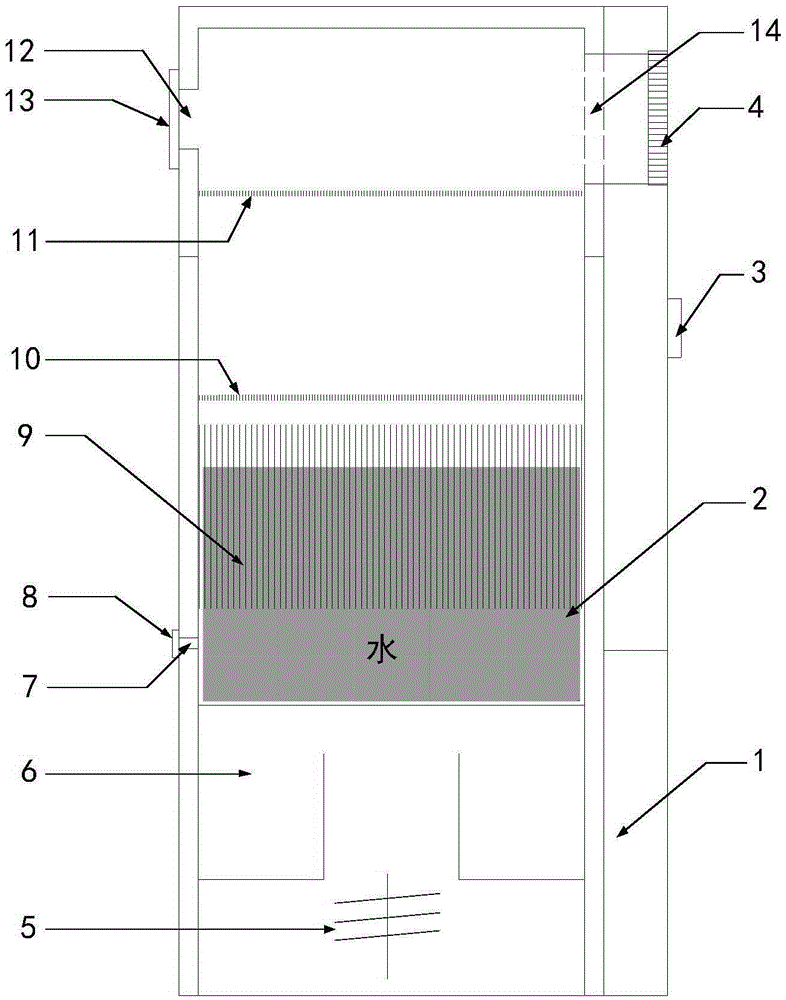
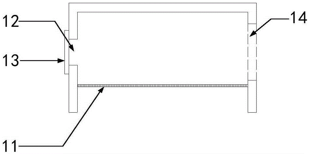
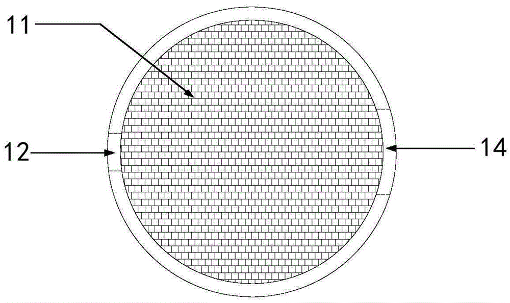
[0022] see Figure 1-3 As shown, the ultrasonic atomization device based on capillary phenomenon of the present invention is composed of an atomizer body and an atomizer cover, including: a power supply 1, a water cup 2, an atomizer switch 3, a diversion fan 4, and a high-frequency vibration source 5 (not less than 1.5MHz), vibration conduction medium 6, water injection hole 7, water injection hole plug 8, capillary hole plug 9, primary microporous screen 10, secondary microporous screen 11, water mist outlet 12, water mist Outlet baffle 13, air inlet 14. The power supply 1 is installed on the bottom of the side wall of the atomizer body, the water cup 2 is set in the cavity of the main body of the atomizer, the atomizer switch 3 is connected to the power supply 1 and installed on the upper part of the power supply 1, the diversion fan 4 and the inlet The a...


PUM


Abstract

An ultrasonic atomization device based on capillarity comprises an atomizer body and an atomizer cover. The atomizer body is cylindrical, and the atomizer cover is in the shape of a cylindrical tube. The atomizer body comprises a high frequency vibration source and a water containing cup inside, and the space between the high frequency vibration source and the water containing cup is filled with an incompressible vibration conduction medium. A power supply, an atomizer switch and a flow guide fan are further arranged on the atomizer body. The water containing cup of the atomizer is of a cylindrical tube structure, the portion, close to the bottom, of the side wall of the water containing cup is provided with a water injection hole and a water injection hole plug, a capillary hole plug is arranged in the water containing cup, the outer diameter of the capillary hole plug is equal to the diameter of the inner wall of the water containing cup, and the capillary hole plug is tightly attached to the inner wall of the water containing cup. A primary micropore filter screen is arranged on the upper portion of the capillary hole plug. A secondary micropore filter screen is arranged on the atomizer cover. The ultrasonic atomization device can be used for forming water spray in a microgravity environment or a totally zero-gravity environment so as to detect the reliability of a smoke alarm and can also be used for regulating the temperature and the humidity within the range of the environment and improving air quality and the like, and the ultrasonic atomization device has the advantages that the ultrasonic atomization device is portable and efficient, and the generated gas spray is clean and free of pollution.

Description

technical field [0001] The invention belongs to the technical field of microgravity, and in particular relates to an ultrasonic atomization device based on capillary phenomenon, which is used for generating safe simulated smoke for detecting smoke alarms in a microgravity or weightless environment. Background technique [0002] Manned spacecraft (manned rockets, spacecraft and space stations, etc.) meet the fire conditions (combustibles, oxygen and possible ignition sources), and there have been many fires in history, so manned spacecraft are equipped with fire smoke detection Therefore, it is necessary to regularly test the fire alarm to confirm whether the alarm is working properly. Usually, the detection of fire smoke alarm function is carried out by using simulated smoke. However, the manned spacecraft is in a microgravity or near-weightless environment and a small confined space, which is completely different from the conventional environment. The simulated smoke is re...

Claims


Application Information

Patent Timeline
Patent Type & Authority Patents(China)
IPC IPC(8): B05B17/06B05B15/00
CPCB05B17/0607B05B17/0653B05B17/0684
Inventor 张永明赵兰明方俊王进军秦俊赵恒泽
Owner UNIV OF SCI & TECH OF CHINA
Why Eureka
Try Eureka