A pipe cutting device

A cutting device and pipe technology, applied in broaching device, broaching machine, metal processing equipment and other directions, can solve the problems of equipment instability, fighting with each other, etc., and achieve the effect of compact structure, high production efficiency and short time consumption

Active Publication Date: 2016-08-17
SUZHOU AOZHI INTELLIGENT EQUIP CO LTD
View PDF7 Cites 0 Cited by
  • Summary
  • Abstract
  • Description
  • Claims
  • Application Information

AI Technical Summary

Problems solved by technology

There is a set of oil cylinders in this mechanism, and the sequence of actions needs to be strictly controlled by the program, otherwise there will be fighting with each other, which will easily cause the instability of the equipment

Method used


Image

  • A pipe cutting device
  • A pipe cutting device
  • A pipe cutting device

Examples


Embodiment Construction

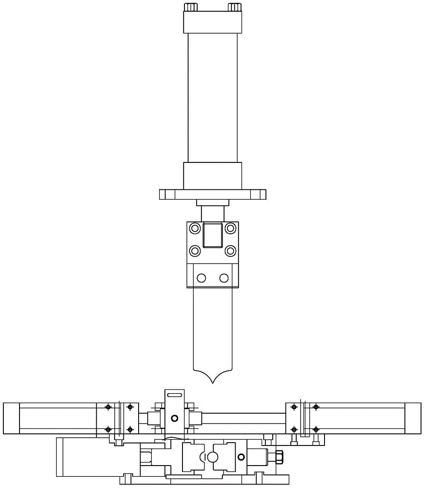
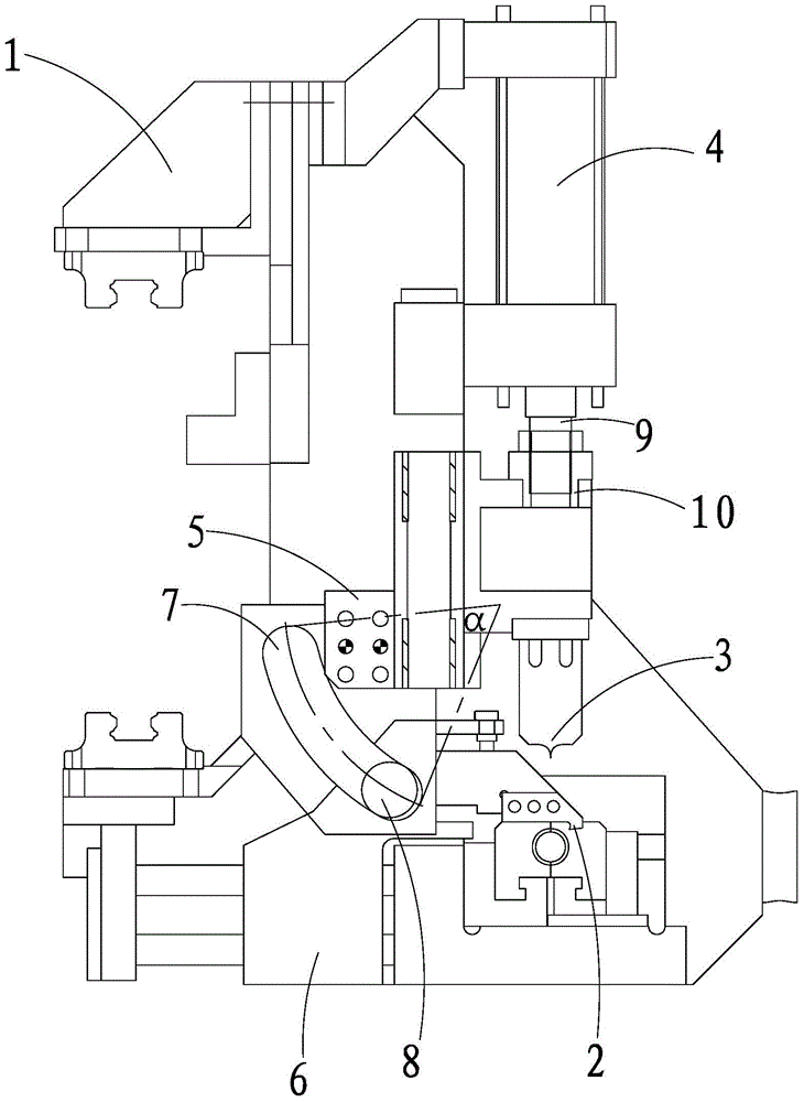
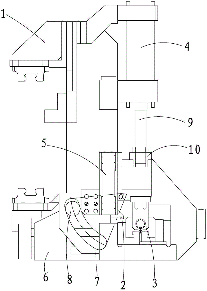
[0019] As shown in the figure, a pipe cutting device includes a frame 1 , A broach that can pull the pipe out of the gap 2 , A punching knife that can cut off the notched pipe 3 , The pipe cutting device also includes installed on the frame 1 Can drive the punch 3 A power source that moves up and down 4 , Used to power source 4 With broach 2 Drive connection so that the broach 2 A transmission mechanism that moves in the forward and backward directions. In power source 4 Driven by the drive and the transmission mechanism, in the punch 3 When moving down, the broach 2 Move backward; punch 3 When moving upward, the broach 2 Move forward; during the whole movement, the broach 2 With punch 3 not in contact.

[0020] The transmission mechanism includes the power source 4 Power source 4 Active block that drives to move up and down 5 Active block 5 Drive movement and can be slid in the front and rear directions on the frame 1 Follower block 6 , Broach 2 Installed ...


PUM


Abstract

The invention relates to a pipe material cutting device, which includes a frame, a broach capable of pulling the pipe out of the gap, and a punching knife capable of cutting the pipe pulled out of the gap. The pipe material cutting device also includes a A power source on the rack and capable of driving the punching knife to move up and down, for connecting the power source to the broach in transmission so as to make the broach move forward and backward transmission mechanism. The present invention only uses one power source, and realizes the linkage between the broach and the punching knife through the transmission mechanism, so that the structure of the cutting device is more compact; and, since only one power source can be controlled, the arrangement of the structure makes the two knives never It will interfere, making the stability of the whole structure stronger; the whole punching process takes less time, and the production efficiency is high; the cutting process time is short, and a good pipe cut can be obtained.

Description

Technical field [0001] The invention involves a pipe cutting device. Background technique [0002] During the production process of metal pipes and rods, cutting is a very critical process. When producing straight pipes and straight rods, the performance of the cutting machine plays a key role. [0003] The structure of the general cutting machine is shown in Figure 1: the mechanism has a knife, a knife, and another knife, and two knives are driven by an independent oil cylinder.When using it, install the tank with a knife first and back, pull the pipe out of a gap, and then install the tank of the knife and move it up and down to cut the pipe.There is a set of cylinders in this institution. The order of action needs to be strictly controlled by the procedures, otherwise there will be a situation of fighting with each other, which will easily cause the instability of the equipment. Invention content [0004] The technical problem to be solved by the present invention is to provi...

Claims


Application Information

Patent Timeline
Patent Type & Authority Patents(China)
IPC IPC(8): B21D28/02B23D37/00
Inventor 顾建刚肖建良莫凯钻
Owner SUZHOU AOZHI INTELLIGENT EQUIP CO LTD
Why Eureka
Try Eureka