Float-type automatic control flap valve

A buoy type, door body technology, applied in the direction of control valves, functional valve types, valve details, etc., can solve the problems of large overflow water damage, poor door sealing performance, water flow energy loss, etc., to reduce water damage and avoid leakage Effect

Active Publication Date: 2014-10-29
WUHAN SHENGYU DRAINING SYST
View PDF6 Cites 2 Cited by
  • Summary
  • Abstract
  • Description
  • Claims
  • Application Information

AI Technical Summary

Problems solved by technology

[0002] The existing flap door cannot be intelligently and automatically controlled, and has little flexibility. Due to the heavy weight of the door panel itself and the poor sealing performance after closing the door, it will cause a large energy loss to the passing water flow and the gap between the door panel and the door body when the door is closed. Strong impact and leakage of water body after closing the door, etc., and the opening force of the existing flap door after installation, and the flatness between the door panel and the sealing surface of the door body after closing the door are difficult to guarantee, so the large water loss caused by overflow is The main drawback of the existing flap door

Method used


Image

  • Float-type automatic control flap valve
  • Float-type automatic control flap valve
  • Float-type automatic control flap valve

Examples


Embodiment Construction

[0014] The present invention will be further described in detail below in conjunction with the accompanying drawings and specific embodiments to facilitate a clear understanding of the present invention, but they do not limit the present invention.

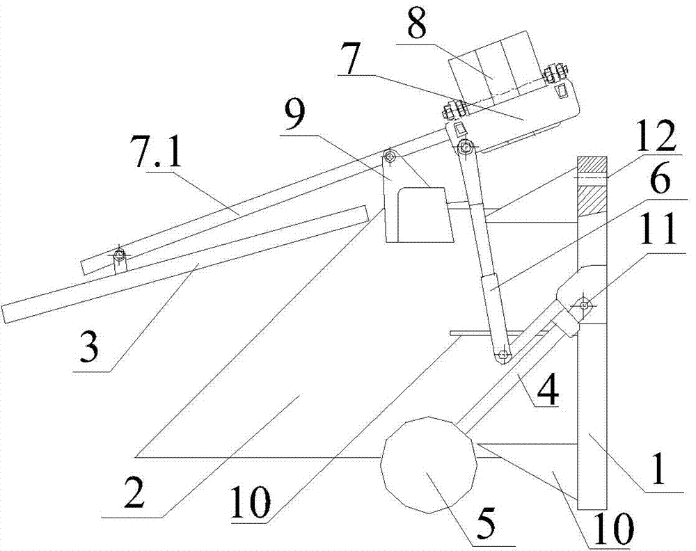
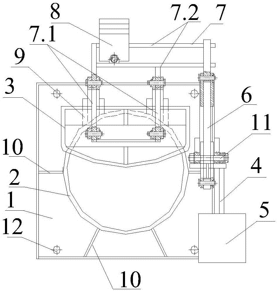
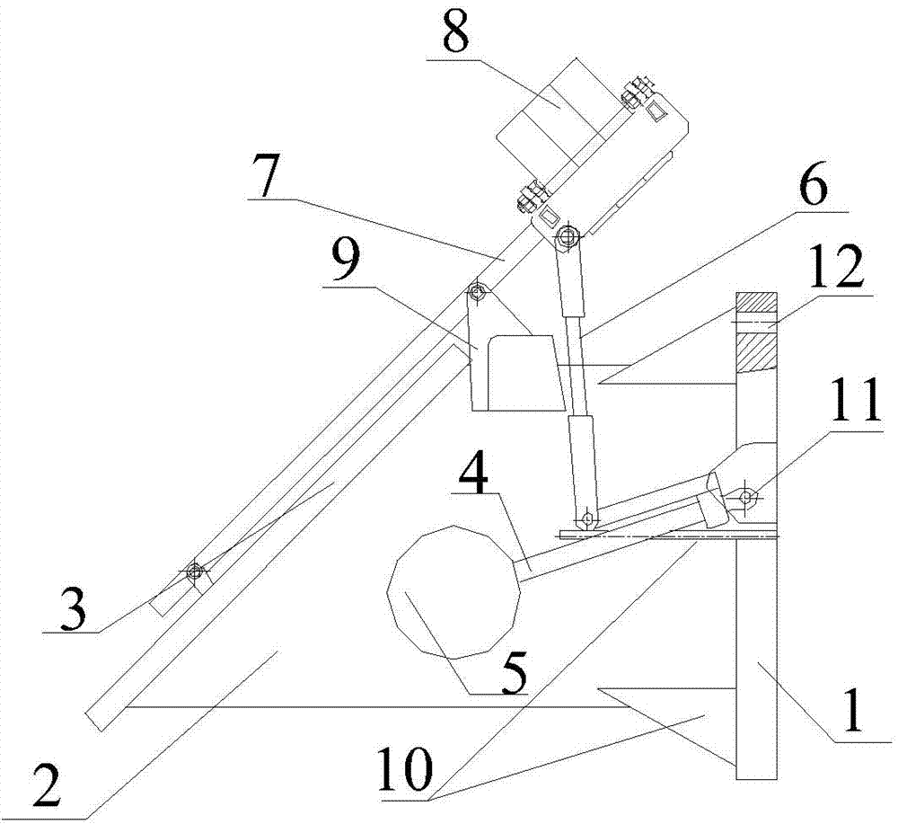
[0015] Such as figure 1 — Figure 4 As shown, the present invention includes a door body 1 with a flow channel, a cylindrical pipe body 2 is fixed on the outer wall of the door body 1, and the longitudinal center section of the pipe body 2 is a trapezoidal structure with a short top end and a long bottom end. The outer end surface of the pipe body 2 forms an inclined flow channel mouth; the outer side of the door body 1 is hinged with one end of the pole 4 through the rotating shaft 11, the other end of the pole 4 is fixed with the cylindrical buoy 5, and the pole 4 is connected with the One end of the hinged door body 1 is fixed to one end of the connecting rod 6, the other end of the connecting rod 6 is hinged to one end of the...


PUM


Abstract

The invention relates to a float-type automatic control flap valve and belongs to the technical field of water supply and drainage equipment. The float-type automatic control flap valve comprises a valve body with a flow pass, a cylindrical pipe is fixed to the outer wall of the valve body, the center section in the longitudinal direction of the pipe is of a trapezoidal structure with the short top end and the long bottom end, an inclined flow pass port is formed in the outer end face of the pipe, the outer side of the valve body is hinged to one end of a support rod, the other end of the support rod is fixedly connected with a float, the end, hinged to the valve body, of the support rod is fixedly connected with one end of a connection rod, the other end of the connection rod is hinged to one end of a balance weight lever frame, the end, hinged to the connection rod, of the balance weight lever frame is fixedly provided with a balance weight, the middle section of the balance weight lever frame is hinged to the outer wall of the top of the pipe, and the other end of the balance weight lever frame is hinged to the outer side of a valve plate. When the valve plate is closed, the inner side of the valve plate makes contact with the outer end face of the pipe in a sealed mode. The float-type automatic control flap valve is provided with the stainless steel float and the balance weight lever frame, and the valve plate is controlled to be opened or closed according to the water level.

Description

technical field [0001] The invention belongs to the technical field of water supply and drainage equipment, and in particular relates to a buoy type self-control flapping door. Background technique [0002] The existing flap door cannot be intelligently and automatically controlled, and has little flexibility. Due to the heavy weight of the door panel itself and the poor sealing performance after closing the door, it will cause a large energy loss to the passing water flow and the gap between the door panel and the door body when the door is closed. Strong impact and leakage of water body after closing the door, etc., and the opening force of the existing flap door after installation, and the flatness between the door panel and the sealing surface of the door body after closing the door are difficult to guarantee, so the large water loss caused by overflow is The major drawback of existing flap doors. Contents of the invention [0003] The object of the present invention ...

Claims


Application Information

Patent Timeline
Patent Type & Authority Applications(China)
IPC IPC(8): F16K15/03F16K15/18F16K31/20F16K31/44
CPCF16K31/24F16K15/1821
Inventor 周超
Owner WUHAN SHENGYU DRAINING SYST
Why Eureka
Try Eureka