Novel rotary kiln body

A rotary kiln, kiln body technology, applied in the direction of rotary drum furnace, furnace type, furnace, etc., can solve the problems of accelerated chemical reaction speed, economic loss, surface temperature rise, etc., to slow down the transfer speed, reduce production cost, temperature reduced effect

Inactive Publication Date: 2014-10-29
安景坡
View PDF5 Cites 0 Cited by
  • Summary
  • Abstract
  • Description
  • Claims
  • Application Information

AI Technical Summary

Problems solved by technology

[0002] At present, in the cement, chemical, and metallurgical industries, a kind of equipment often used by manufacturers is the rotary kiln. This rotary kiln is mainly composed of a kiln shell, rolling rings, transmission gears and heat-resistant bricks. Among them, the kiln shell is made of steel plates. The heat-resistant bricks are built on the inner side of the kiln shell to form a heat-resistant layer, which provides an insulating environment for the manufacture of cement, chemical products, and metallurgical workpieces. However, a large number of practices show that this two-layer structure of the rotary kiln body There are many deficiencies, such as: the thermal conductivity of heat-resistant bricks is relatively large. During the production process, heat-resistant bricks will transfer a large amount of heat to the atmosphere through the kiln shell, resulting in a large amount of energy loss. At the same time, due to heat-resistant bricks The conduction effect of the kiln shell greatly increases the surface temperature of the kiln shell, which accelerates the chemical reaction speed of the steel plate of the kiln shell with oxygen and corrosive gases in the air, and also accelerates the damage progress of the rotary kiln shell, resulting in unsightly necessary economic loss

Method used


Image

  • Novel rotary kiln body
  • Novel rotary kiln body
  • Novel rotary kiln body

Examples


Embodiment Construction

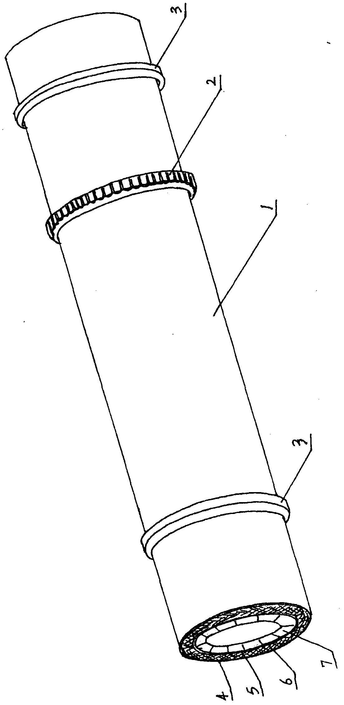
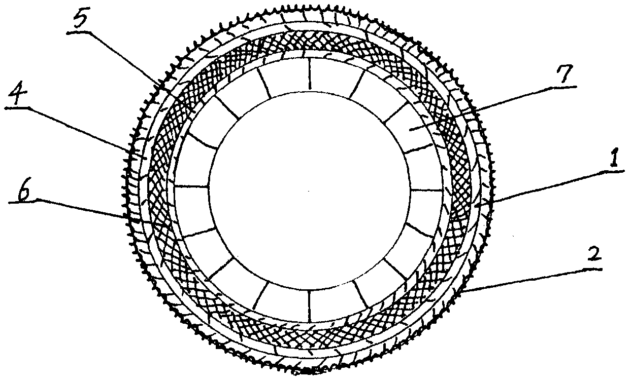
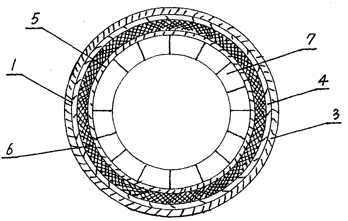
[0011] exist figure 1 Among them, 1. Rotary kiln body; 2. Transmission gear; 3. Rolling ring; 4. Outer cylinder; 5. Inner cylinder; 6. Zirconium-aluminum cotton insulation board; 7. Heat-resistant brick.

[0012] exist figure 1 Among them, a new type of rotary kiln body 1 of the present invention includes a transmission gear 2, a rolling ring 3, an outer cylinder 4, an inner cylinder 5, a zirconium-aluminum wool thermal insulation board 6, and heat-resistant bricks 7. Among them: the inner cylinder is formed by rolling and welding heat-resistant steel plates with a thickness of 4 mm, and the outer cylinder 4 is provided with a rolling ring 3 and a transmission gear 2, which are connected to the outer cylinder 4 by welding, Between the outer cylinder body 4 and the inner cylinder body 5, zirconium-aluminum wool thermal insulation boards 6 are filled, and on the inner circumference of the inner cylinder body 5, heat-resistant bricks 7 are evenly laid.

[0013] exist figure 2...


PUM


Abstract

The invention relates to a rotary kiln body, in particular to a novel rotary kiln body used for rotary kilns in the industries of cement, chemical engineering and metallurgy. The novel rotary kiln body is mainly composed of a transmission gear, rolling rings, an inner barrel, an outer barrel, zirconium-aluminum cotton heat insulation plates, annular inner barrel supports and heat-resisting bricks. The inner barrel and the outer barrel are both formed by rolling and welding a heat-resisting steel sheet, the annular inner barrel supports and the zirconium-aluminum cotton heat insulation plates are arranged between the inner barrel and the outer barrel, the heat-resisting bricks are arranged on the inner periphery of the inner barrel, the rolling rings and the transmission gear used for enabling the kiln body to rotate are arranged on the periphery of the outer barrel, and the rolling rings and the transmission gear are welded with the outer barrel. Due to the technical scheme, the heat insulation layer composed of the inner barrel, the annular inner barrel supports and the zirconium-aluminum cotton heat insulation plates is added between the heat-resisting bricks and the outer barrel, and the purposes of guaranteeing temperature in the kiln body, improving production efficiency, lowering energy consumption and prolonging the service life of the kiln body are achieved.

Description

technical field [0001] The invention relates to a rotary kiln body, which mainly refers to a new type of rotary kiln body used in cement, chemical industry and metallurgical rotary kilns. Background technique [0002] At present, in the cement, chemical, and metallurgical industries, a kind of equipment often used by manufacturers is the rotary kiln. This rotary kiln is mainly composed of a kiln shell, rolling rings, transmission gears and heat-resistant bricks. Among them, the kiln shell is made of steel plates. The heat-resistant bricks are built on the inner side of the kiln shell to form a heat-resistant layer, which provides an insulating environment for the manufacture of cement, chemical products, and metallurgical workpieces. However, a large number of practices show that this two-layer structure of the rotary kiln body There are many deficiencies, such as: the thermal conductivity of heat-resistant bricks is relatively large. During the production process, heat-resi...

Claims


Application Information

Patent Timeline
Patent Type & Authority Applications(China)
IPC IPC(8): F27B7/22
Inventor 安景坡
Owner 安景坡
Why Eureka
Try Eureka