Intelligent distributed feeder automation logic test system

A feeder automation and test system technology, applied in the direction of measuring electricity, measuring devices, measuring electrical variables, etc., can solve problems such as different software, few types of test faults, and complex on-site conditions

Active Publication Date: 2014-10-29
SHANGHAI MUNICIPAL ELECTRIC POWER CO +1
View PDF4 Cites 28 Cited by
  • Summary
  • Abstract
  • Description
  • Claims
  • Application Information

AI Technical Summary

Problems solved by technology

[0004] However, since the feeder automation (FA) equipment has undergone type tests and logic tests before being put into operation, the laboratory test uses the switch-network cable direct connection method for communication, which is not completely consistent with the actual communication conditions on site; in addition, the temperature of the laboratory test The wet environment is also inconsistent with the field; after the equipment is put into operation, the grid and configuration changes and the test needs to be re-tested in the laboratory; therefore, logic tests need to be carried out on-site. In the initial stage, manual on-site testing is adopted, using walkie-talkies There is a large error in the timing, and the manual test consumes a lot of manpower and takes too long, and there are few types of faults that can be tested
[0005] In addition, during the installation, commissioning and operation of automation equipment, it was found that due to the large variety of equipment and complex on-site conditions, there were problems such as unclear processes in on-site construction and commissioning, and there were many manufacturers with different software, lacking a standardized commissioning process

Method used


Image

  • Intelligent distributed feeder automation logic test system
  • Intelligent distributed feeder automation logic test system
  • Intelligent distributed feeder automation logic test system

Examples


Embodiment Construction

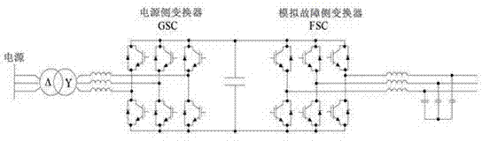
[0037] The invention provides an intelligent distributed feeder automatic logic test system (hereinafter referred to as the test system), which includes a fault simulator, a switch simulator and a communication interface.

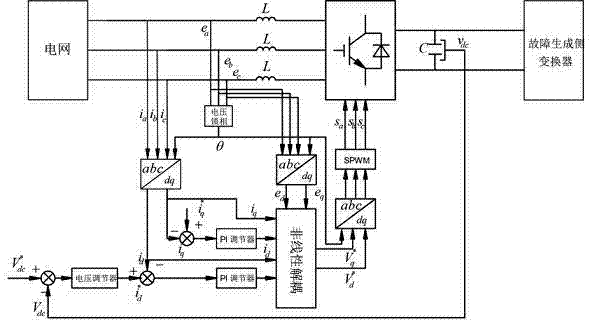
[0038] Wherein, the fault simulator is composed of a Back to Back (back to back) voltage type PWM converter structure. The schematic diagram of the topological circuit is as follows: figure 1 shown. Since two three-phase PWM voltage-type converters are used to form the main circuit of the fault simulator through Back to Back connection, the characteristics of the power supply under normal and various fault conditions can be used to test and detect the power supply connected to the power distribution terminal. Troubleshooting capabilities.

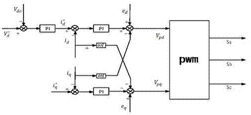
[0039] Taking the power-side converter GSC of the fault simulator as an example, the PWM rectifier can not only make the input current sinusoidal, the power factor is 1 or adjustable, but also can make the energy flow ...


PUM


Abstract

The invention relates to an intelligent distributed feeder automation logic test system. According to the intelligent distributed feeder automation logic test system, the normal working or the fault state of a tested loop is simulated, a voltage signal and/or a current signal is generated by a fault simulator, a corresponding switching value signal is generated by a switch simulator and sent to a power distribution terminal in the tested loop through a communication interface as a test signal, the power distribution terminal feeds the switching state information formed according to the test signal back to the test system through the communication interface, and an ordered, accurate and efficient intelligent distributed feeder automation logic test for the power distribution terminal is realized by judging whether the switching state information meets processing logic during the normal working or the fault state of the tested loop.

Description

technical field [0001] The invention relates to the field of power distribution automation, in particular to an intelligent distributed feeder automation logic test system. Background technique [0002] Distribution automation is the use of modern electronics, computers, communications and network technologies to integrate the online and offline data, distribution network data and user data, power grid structure and geographic graphics of the distribution network to form a complete automation system. The modernization of monitoring, protection, control, power consumption and distribution management of power grid and its equipment in normal operation and accident state. Distribution network automation is a stage in the development process of power system automation. The distribution network that implements distribution network automation generally refers to the medium and low voltage distribution network of 10kV and below that directly faces end users. [0003] Intelligent d...

Claims


Application Information

Patent Timeline
Patent Type & Authority Applications(China)
IPC IPC(8): G01R31/00
Inventor 杨光张可邱名义张钻王何舟谢邦鹏史益毛雅玲
Owner SHANGHAI MUNICIPAL ELECTRIC POWER CO
Why Eureka
Try Eureka