
Electronic control device for multi-rotor aircraft, electronic control device for aerial photography of multi-rotor aircraft and follow-up aerial photography multi-rotor aircraft

A multi-rotor aircraft and electronic control device technology, applied in aircraft, measuring devices, three-dimensional position/course control, etc., can solve the problems of missing wonderful moments, unable to achieve follow-up, and unable to achieve follow-up, etc.

Active Publication Date: 2017-09-22
ZHEJIANG FEISHEN VEHICLE IND CO LTD
View PDF9 Cites 0 Cited by
  • Summary
  • Abstract
  • Description
  • Claims
  • Application Information

AI Technical Summary

Problems solved by technology

[0004] Although the current multi-rotor aircraft already has many functions and expansions, as aerial photography in the air, there is still a relatively large functional shortcoming, that is, it cannot achieve follow-up photography during the aerial photography process, which affects the continuity of aerial photography
Especially for aerial photography of outdoor moving objects, many wonderful moments are missed because of the inability to follow

Method used


Image

  • Electronic control device for multi-rotor aircraft, electronic control device for aerial photography of multi-rotor aircraft and follow-up aerial photography multi-rotor aircraft

Examples


Embodiment Construction

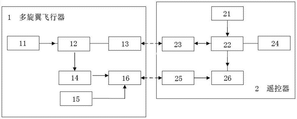
[0017] refer to figure 1 The electronic device for aerial photography of the multi-rotor aircraft includes a first GPS positioning receiver 11, which is installed in the multi-rotor aircraft 1 and carries out real-time positioning of its geographical position; the aircraft control chip 12 connected with the first positioning receiver 11, and connected The first transceiver antenna 13 of the aircraft control chip 12, and the motion camera 15 for aerial photography; the second GPS positioning receiver 21, is installed in the remote controller 2 for manipulating the multi-rotor aircraft 1 and carries out real-time positioning to its geographic position ; connect the main control chip 22 of the second positioning receiver, and connect the second transceiver antenna 23 of the main control chip 22, and a mode selection switch (not shown) for switching the aerial photography state; wherein the The aircraft controller 12 controls the first positioning receiver 11 to obtain its geograp...


PUM


Abstract

The invention discloses an aerial shooting electronic device of a multi-rotor aircraft. The aerial shooting electronic device comprises a first locating receiver used for instantly locating the geographical position of the multi-rotor aircraft, an aircraft control chip connected with the first locating receiver, a first transceiver antenna connected with the aircraft control chip, a motion camera used for aerial shooting, a second locating receiver used for instantly locating the geographical position of a remote controller, a main control chip connected with the second locating receiver, a second transceiver antenna connected with the main control chip, and a mode selection switch used for switching the aerial shooting state. An aircraft controller controls the first locating receiver to acquire the geographical position information of the aircraft controller, the geographical position information is sent through the first transceiver antenna to the second transceiver antenna to enable the main control chip to acquire and judge the position information and control the multi-rotor aircraft to fly toward the geographical position of the remote controller, and multiple times of aerial shooting are carried out in the flying process. The invention further discloses a multi-rotor aircraft electronic control device and an aerial shooting following multi-rotor aircraft.

Description

technical field [0001] The present invention mainly relates to an electronic control device of an aircraft, more specifically, relates to an electronic control device of a multi-rotor aircraft with the function of following aerial photography. Background technique [0002] With the rapid development of science and technology, the market for multi-wing aircraft products that have emerged recently is booming. With its extraordinary stability and maneuverability, multi-rotor aircraft has gradually replaced the traditional two-screw and single-screw aircraft, especially its application in actual production and life has increased the market recognition of this product. Its practical application in many fields will have a profound impact on future production and life. [0003] At present, the existing technical solutions use 4-12 brushed or brushless motors as power, brushed or brushless electronic governors as drives, ultra-long-distance transmitters and receivers as transceiver...

Claims


Application Information

Patent Timeline
Patent Type & Authority Patents(China)
IPC IPC(8): G05D1/10G01S19/42B64C39/02B64C39/08G08C17/02
Inventor 丁建峰陈曼天芮章杰陈向阳汤敏
Owner ZHEJIANG FEISHEN VEHICLE IND CO LTD
Learn More