DC interrupter interrupter

A DC breaking and arc-extinguishing chamber technology, applied in high-voltage/high-current switches, electric switches, high-voltage air circuit breakers, etc., can solve the problems affecting the breaking capacity of arc extinguishing devices, increase the contact area, and increase the pressure gas reaction force and other problems to achieve the effect of reducing burden, improving reliability, and reducing pressure reaction force

Active Publication Date: 2016-08-10
STATE GRID CORP OF CHINA +3
View PDF6 Cites 2 Cited by
  • Summary
  • Abstract
  • Description
  • Claims
  • Application Information

AI Technical Summary

Problems solved by technology

[0003] However, when it is necessary to increase the flow capacity of the arc extinguishing device, in order to ensure the flow area between the pressure cylinder and the moving contact, the diameter of the pressure cylinder needs to be increased, because the moving contact seat and the inner wall of the pressure cylinder need to maintain a sliding and sealing fit , increasing the diameter of the compressed air chamber will lead to an increase in the contact area between the moving contact seat and the gas in the compressed air chamber, which will increase the compressed air reaction force during the opening process, and the corresponding operating device needs to provide a larger More power and more operating work, higher requirements on the operating device, but also affect the breaking capacity of the arc extinguishing device

Method used


Image

  • DC interrupter interrupter
  • DC interrupter interrupter
  • DC interrupter interrupter

Examples


Embodiment Construction

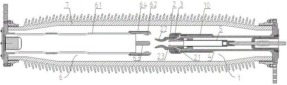
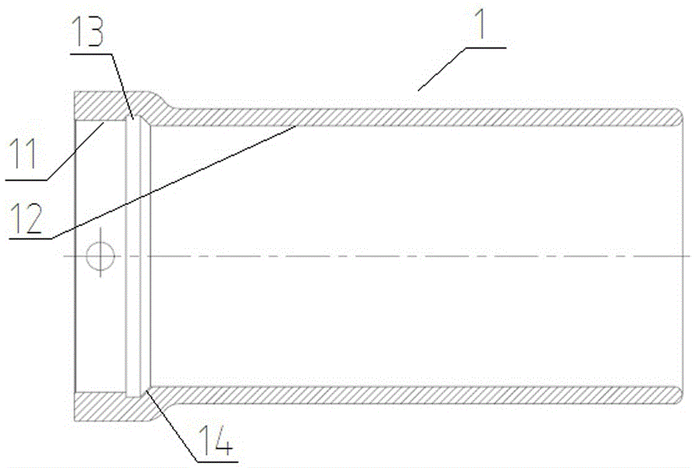
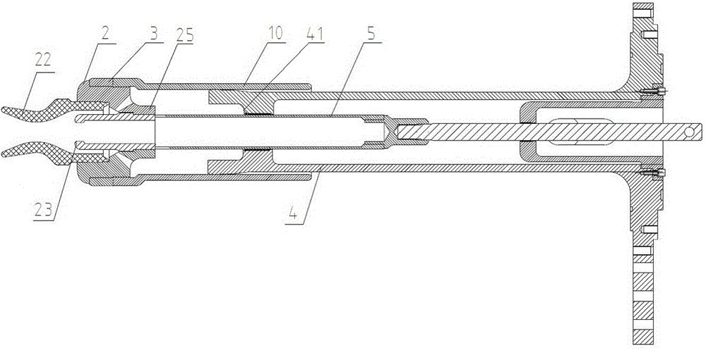
[0016] An embodiment of the arc extinguishing chamber of the DC breaking device of the present invention is Figure 1~Figure 4 As shown, it is used for UHV DC transfer switch to realize arc extinguishing when breaking DC current. The arc extinguishing device includes a porcelain sleeve 7 , a static end assembly 6 and a moving end assembly 1 . The static end assembly 6 includes a static contact seat 61, a static contact finger 62, a static arc contact 63 and a shield cover 64. The moving end assembly 1 includes a moving contact device, a pressure cylinder 10, a moving contact seat 4 and a drive rod 5. The contact device includes a moving contact body 2 and a conductive slip ring 3 sheathed on the outer peripheral surface of the moving contact body 2 . The moving contact body 2 is provided with a gas channel 21 , and is fixed with a nozzle 22 corresponding to the front opening of the gas channel 21 , and is also conductively connected with a moving arc contact 23 . In order to...


PUM


Abstract

The invention relates to an arc extinguishing chamber of a DC breaking device. The arc extinguishing chamber of the DC breaking device includes a static end assembly and a moving end assembly, the moving end assembly includes a moving contact device, a pressure cylinder and a nozzle, the moving contact device includes a moving contact body, and the pressure cylinder includes a cylindrical cylinder body , the front part of the inner peripheral wall of the cylinder body has a movable contact mating section which is sleeved on the corresponding outer peripheral surface of the movable contact body and electrically connected with the movable contact body, and the rear part of the inner peripheral wall has a corresponding movable contact seat The moving contact seat matching section of the guide assembly, the inner diameter of the moving contact fitting section is larger than the inner diameter of the moving contact seat matching section, and there is an inner diameter between the moving contact fitting section and the moving contact seat matching section. The rear end opening of the gas channel in the contact device corresponds to the flaring structure, and the nozzle is fixed on the moving contact body corresponding to the front opening of the gas channel. The above-mentioned arc extinguishing chamber of the direct current breaking device can reduce the pressure and gas reaction force, reduce the burden of the operating mechanism, and reduce its operating work under the condition of meeting the flow capacity.

Description

technical field [0001] The invention relates to an arc extinguishing chamber of a DC breaking device. Background technique [0002] Existing arc extinguishing devices, such as the improved self-energy SF6 circuit breaker disclosed by the Chinese patent application number 201120054008.8 and announcement number CN 202058636 U, include static end components and moving end components, and the dynamic The end assembly includes a moving contact device, a pressure cylinder, a moving contact seat and a transmission rod that drives the moving contact to move in the opening and closing direction. The main contact, the moving main contact is ring-shaped and has an outer peripheral surface used to slide and conduct electricity with the static contact finger in the static end assembly, and its inner ring wall is fixedly connected with a nozzle for blowing out the arc. Among them, the pressure cylinder is the key component of the arc extinguishing device. It not only serves as the main c...

Claims


Application Information

Patent Timeline
Patent Type & Authority Patents(China)
IPC IPC(8): H01H33/91
Inventor 孙珂珂程铁汉马志华门博
Owner STATE GRID CORP OF CHINA
Why Eureka
Try Eureka