
Solar cell module EL testing device and method under visible light

A solar cell and visible light technology, applied in photovoltaic power generation, electrical components, photovoltaic system monitoring and other directions, can solve the problems of inability to carry out outdoor testing, inconvenience to carry, complex equipment, etc., to achieve low cost, convenient outdoor use, and reduce equipment costs Effect

Inactive Publication Date: 2014-11-05
HEBEI NAT LIGHTING PHOTOELECTRIC TECH CO LTD
View PDF4 Cites 3 Cited by
  • Summary
  • Abstract
  • Description
  • Claims
  • Application Information

AI Technical Summary

Problems solved by technology

[0003] The present invention proposes a device and method for testing the EL of solar cell modules under visible light. Its purpose is to solve the problem of the need to equip a professional CCD infrared camera and dark box in the existing solar cell module EL test. The equipment is complex, Disadvantages such as high cost, inconvenient portability, and inability to conduct outdoor tests

Method used


Image

  • Solar cell module EL testing device and method under visible light
  • Solar cell module EL testing device and method under visible light

Examples


Embodiment

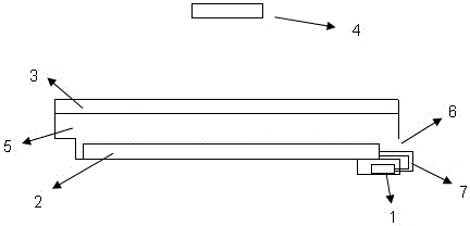
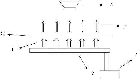
[0029] At one end of the cavity 5 for placing the solar cell module 2, there is a cavity inlet 6 for entering and exiting the solar cell module 2; the transparent material 3 containing the up-conversion material is fixed above the cavity by means of a mounting groove, and the power supply 1 It is fixed under the cavity and connected to the solar cell module through the wire 7. When the power supply 1 applies the corresponding voltage according to the specific model of the solar cell module 2, the solar cell module 2 electroluminescently generates infrared light of 800nm─1300nm. The transparent material 3 converts the emitted infrared light 8 into visible light 9, and uses the camera 4 to take pictures for detection, and detects the defect type according to the difference in luminance.

[0030] The up-conversion material is a light-wave conversion material that can absorb 800nm-1300nm infrared light and emit visible light, preferably an up-conversion luminescent material doped w...


PUM


Abstract

The invention discloses a solar cell module EL testing device and method under visible light. The solar cell module EL testing device structurally comprises a power source 1, a solar cell module 2, transparent materials 3 containing up-conversion materials, a camera 4, a cavity 5, a cavity inlet 6 and a wire 7, wherein the power source 1 is fixed below the cavity and connected with the solar cell module 2 through the wire 7, the transparent materials 3 containing the up-conversion materials are fixed to the cavity 5, the cavity inlet 6 is reserved in one end of the cavity 5 and used for enabling the solar cell module 2 to enter or exit from the cavity 5, and the camera 4 is installed above the transparent materials 3 containing the up-conversion materials. The solar cell module EL testing device has the advantages that the up-conversion materials convert infrared light obtained through electroluminescence of the solar cell module into the visible light, a common visible light camera can be used for photographing, no special darkrooms are needed, the whole structure is simple, the cost is low, and the solar cell module EL testing device is convenient to carry for outdoor use.

Description

technical field [0001] The invention relates to an EL test device and a test method for solar cell components under visible light, and belongs to the field of solar cell component detection. Background technique [0002] During the production and use of solar cell modules, defects such as splits, low-efficiency sheets, and local defects in cells often occur. At present, the detection of this kind of defect is mainly based on the electroluminescence principle (EL phenomenon) of solar cells, and the defect type is detected according to the difference in luminous brightness of the cells in the solar cell module after being energized. However, since the wavelength range of electroluminescence of solar cell modules is 800nm ​​to 1300nm, it needs to be equipped with a professional CCD infrared camera for shooting and a special box to form a darkroom. The overall structure is complex, the manufacturing cost is high, and it is not convenient to carry it outdoors. use. The inventio...

Claims


Application Information

Patent Timeline
Patent Type & Authority Applications(China)
IPC IPC(8): H02S50/15
CPCY02E10/50
Inventor 朱明甫张明昌刘大鹏牛志勇赵文俊
Owner HEBEI NAT LIGHTING PHOTOELECTRIC TECH CO LTD
Learn More