Backup power source device and automobile equipped with same
A backup power supply and charging circuit technology, applied in the automotive field, can solve problems such as inability to provide starting voltage
- Summary
- Abstract
- Description
- Claims
- Application Information
AI Technical Summary
Problems solved by technology
Method used
Image


Examples
Embodiment approach 1
[0025] figure 1 It is a block diagram showing an example of the backup power supply device according to Embodiment 1 of the present invention. The backup power supply device 15 includes a capacitor 25 , a charging circuit 26 , a voltage boosting circuit 27 , and a door unlock output terminal 28 . The charging circuit 26 is provided on the charging path of the capacitor 25 and lowers the input voltage of the charging circuit 26 . The boost circuit 27 is provided on the output path of the capacitor 25 . Furthermore, the door lock release output terminal 28 is connected to the booster circuit 27 .
[0026] With the above configuration, the backup power supply device can appropriately output electric power for unlocking the door from the door unlock output terminal in an emergency.
[0027] That is, when the battery 22 is damaged due to an accident or the like (see Figure 4 ) is damaged, etc., the booster circuit 27 boosts the voltage of the capacitor 25, and supplies the bo...
Embodiment approach 2
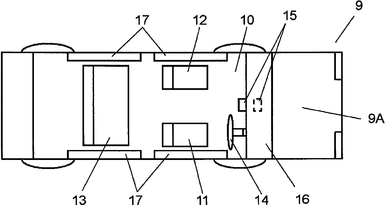
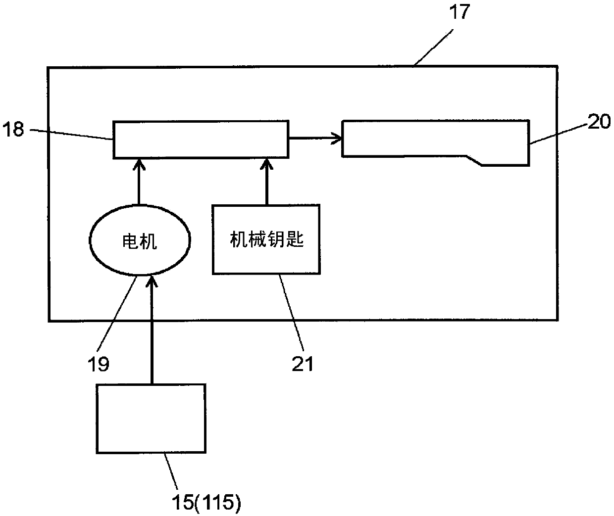
[0074] Figure 9 It is a block diagram showing an example of connection between a backup power supply device according to Embodiment 2 of the present invention and an automobile equipped with the backup power supply device. Hereinafter, an embodiment of the connection between the backup power supply device 115 and the vehicle on which the backup power supply device 115 is mounted will be described. Of course, the standby power supply device 115 is also configured in figure 2 An interior 10 of a car 9 is shown. In addition, the same code|symbol is attached|subjected to the same structure as Embodiment 1, and detailed description may be abbreviate|omitted.
[0075] Such as Figure 9 As shown, the charging circuit 26 of the backup power supply unit 115 is provided on the power supply side of the capacitor 25 . Furthermore, the charging circuit 26 charges the capacitor 25 . The booster circuit 27 is provided on the power discharge side of the capacitor 25 . The boost circui...
PUM
 Abstract
Description
Claims
Application Information
 - R&D Engineer
- R&D Manager
- IP Professional
- Industry Leading Data Capabilities
- Powerful AI technology
- Patent DNA Extraction
Browse by: Latest US Patents, China's latest patents, Technical Efficacy Thesaurus, Application Domain, Technology Topic.
© 2024 PatSnap. All rights reserved.Legal|Privacy policy|Modern Slavery Act Transparency Statement|Sitemap