Systems and methods for adjusting current consumption of control chips to reduce standby power consumption of power converters

a control chip and power converter technology, applied in the field of integrated circuits, can solve the problems of increasing the loss of power consumption with the switching frequency, the power consumption of the switch-mode converter can consume significant power under standby conditions, and the energy loss of various components, so as to reduce the power consumption of one or more power consumption components, and reduce the overall standby power consumption of the power converter

Active Publication Date: 2013-01-03
ON BRIGHT ELECTRONICS SHANGHAI
View PDF8 Cites 98 Cited by
  • Summary
  • Abstract
  • Description
  • Claims
  • Application Information

AI Technical Summary

Benefits of technology

[0026]The present invention is directed to integrated circuits. More particularly, the invention provides a system and method for reducing standby power consumption. Merely by way of example, the invention has been applied to a power converter. But it would be recognized that the invention has a much broader range of applicability.
[0030]According to yet another embodiment, a method for regulating a power conversion system includes receiving a feedback signal related to an output signal of a power conversion system, a current sensing signal and an input voltage, the current sensing signal representing one or more peak magnitudes related to a primary current flowing through a primary winding of the power conversion system, processing information associated with the feedback signal, the current sensing signal and the input voltage, and generating a control signal based on at least information associated with the feedback signal, the current sensing signal and the input voltage. The method further includes receiving the control signal, processing information associated with the control signal, and, if the control signal indicates the feedback signal is smaller than a feedback threshold for a first predetermined period of time, the current sensing signal is smaller than a current sensing threshold for a second predetermined period of time, and the input voltage is smaller than a first threshold for a third predetermined period of time in magnitude, reducing power consumption of one or more power consumption components. Each of the first predetermined period of time, the second predetermined period of time, and the third predetermined period of time is equal to or larger than zero in magnitude.
[0031]Many benefits are achieved by way of the present invention over conventional techniques. Certain embodiments of the present invention provide a method to reduce standby power consumption in pulse width modulation (PWM) controlled switch mode power converters including but not limited to an offline fly-back converter, and a forward converter. Some embodiments of the present invention provide a method to intelligently and dynamically manage internal current consumption of a PWM controller IC to reduce the overall standby power consumption of a power converter.
[0032]Certain embodiments of the present invention provide a method to reduce internal current consumption under light load or no load conditions to reduce the overall standby power consumption of a switching power converter. For example, the current consumption of a PWM controller is dynamically managed in response to different load conditions. In another example, the current consumption of the PWM controller is reduced under light load or no load conditions by powering down some functional blocks which are not necessary under those conditions. In yet another example, meanwhile, the current consumption of other function blocks is reduced without degrading dynamic performance of the switching power converter under light load or no load conditions. Charges held on a power-supply holding capacitor supply the PWM controller for a long time without switching thus results in low standby power consumption in some embodiments of the present invention.
[0033]Certain embodiments of the present invention provide a method to manage current consumption of a PWM controller that works in several power modes, such as a normal operation mode, a power saving mode, and a power dissipation mode. For example, in a power saving mode, the current consumption of the PWM controller is reduced in order to reduce standby power consumption. In another example, in a power dissipation mode, the PWM controller consumes more power than in a normal operation mode to prevent a power supply voltage of the PWM controller from drifting high to protect the PWM controller.

Problems solved by technology

The switch-mode converters can consume significant power under standby conditions, such as with light or zero output loads.
In another example, the standby power consumption includes energy losses at various components of the switch-mode converters such as power switches, transformers, inductors, and snubbers.
These losses often increase with the switching frequency.
But if the switching frequency becomes too low and falls within the audio range, unwanted audible noises arise.
But the dummy load consumes a constant power and hence degrades the power efficiency of the converter 100, especially under light or no load conditions.

Method used


Image

  • Systems and methods for adjusting current consumption of control chips to reduce standby power consumption of power converters
  • Systems and methods for adjusting current consumption of control chips to reduce standby power consumption of power converters
  • Systems and methods for adjusting current consumption of control chips to reduce standby power consumption of power converters

Examples


Embodiment Construction

[0048]The present invention is directed to integrated circuits. More particularly, the invention provides a system and method for reducing standby power consumption. Merely by way of example, the invention has been applied to a power converter. But it would be recognized that the invention has a much broader range of applicability.

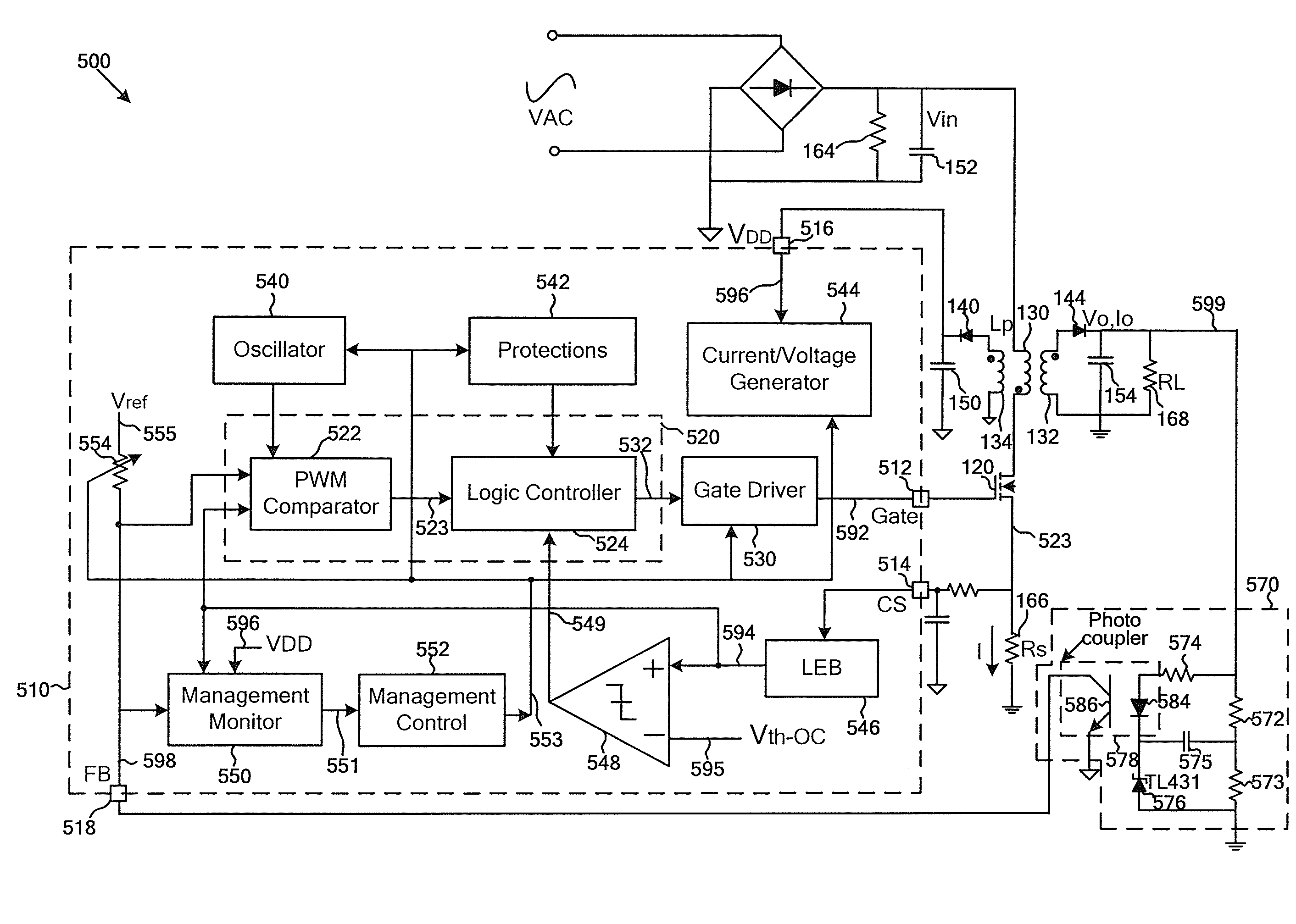
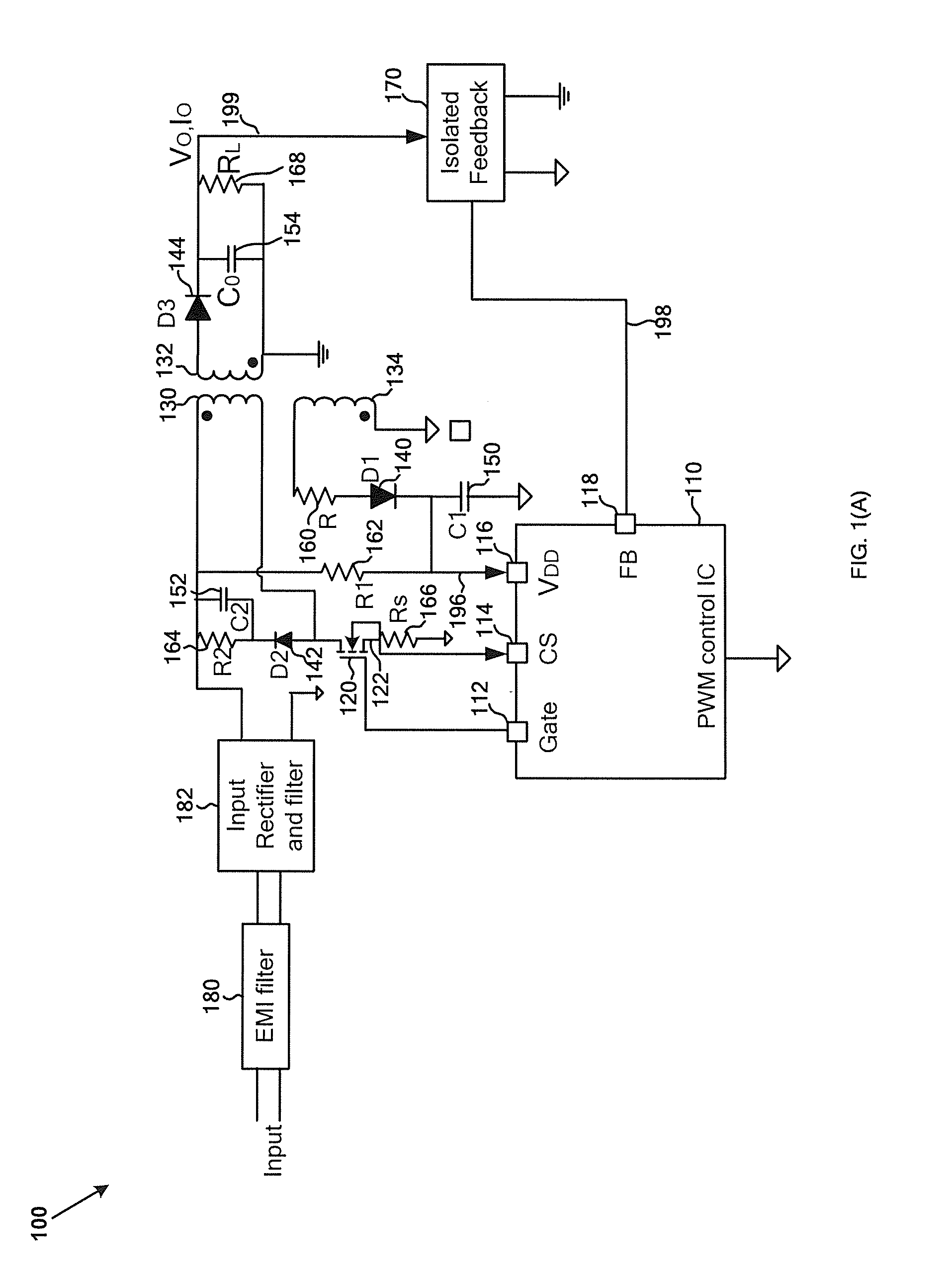
[0049]As discussed above, the dummy load is used to prevent the chip supply voltage 196 (e.g., VDD) from dropping below the UVLO threshold if the charging of the capacitor 150 is insufficient to balance the current consumption of the chip 110. When the power switch 120 is turned off, the drop rate of the chip supply voltage 196 (e.g., VDD) depends on the current consumption of the chip 110.

[0050]If the current consumption of the chip 110 becomes larger, the chip supply voltage VDD drops faster. Consequently, a larger dummy load is needed in order to maintain the balance between charging and discharging of the capacitor 150 and prevent the chip supply volta...


PUM


Abstract

System and method for regulating a power conversion system. For example, a system controller includes a signal generator and one or more power-consumption components. The signal generator is configured to receive a feedback signal related to an output signal of the power conversion system, a current sensing signal and an input voltage, and to generate a control signal based on at least information associated with the feedback signal, the current sensing signal and the input voltage. The power-consumption components are configured to receive the control signal. The signal generator is further configured to determine whether the feedback signal is smaller than a feedback threshold for a first predetermined period of time, the current sensing signal is smaller than a current sensing threshold for a second predetermined period of time, and the input voltage is smaller than a first threshold for a third predetermined period of time in magnitude.

Description

1. CROSS-REFERENCES TO RELATED APPLICATIONS[0001]This application claims priority to U.S. Provisional Application No. 61 / 432,130, filed Jan. 12, 2011, commonly assigned and incorporated by reference herein for all purposes.2. BACKGROUND OF THE INVENTION[0002]The present invention is directed to integrated circuits. More particularly, the invention provides a system and method for reducing standby power consumption. Merely by way of example, the invention has been applied to a power converter. But it would be recognized that the invention has a much broader range of applicability.[0003]Power converters are widely used for consumer electronics such as portable devices. The power converters can convert electric power from one form to another form. As an example, the electric power is transformed from alternate current (AC) to direct current (DC), from DC to AC, from AC to AC, or from DC to DC. Additionally, the power converters can convert the electric power from one voltage level to a...

Claims


Application Information

Patent Timeline
Patent Type & Authority Applications(United States)
IPC IPC(8): H02M3/335
CPCH02M3/33523H02M7/2176Y02B70/16H02M2001/0035H02M2001/0006H02M1/0006H02M1/0035Y02B70/10
Inventor FANG, LIEYI
Owner ON BRIGHT ELECTRONICS SHANGHAI
Why Eureka
Try Eureka