Lumbosacral vertebrae percutaneous pedicle screw placement positioner

A pedicle screw and locator technology, which is applied in the field of medical devices, can solve problems such as difficulty in popularization and application, complicated operation, and expensive equipment, and achieve the effects of shortening X-ray exposure time, shortening operation time, and reducing the number of fluoroscopy times

Inactive Publication Date: 2014-11-12
刘瑾
View PDF8 Cites 26 Cited by
  • Summary
  • Abstract
  • Description
  • Claims
  • Application Information

AI Technical Summary

Problems solved by technology

However, the traditional percutaneous puncture and pedicle screw placement have many limitations and disadvantages. For example, the operation often requires repeated C-arm fluoroscopy guidance or correction to be successfully completed, which increases the burden on the operator and the patient. The amount of x-ray exposure and the prolongation of the operation time make it difficult to guarantee the accuracy of the operation
At present, with the help of computer-aided virtual X-ray navigation technology, CT scan navigation, and ultrasound scan navigation, the insertion of percutaneous pedicle screws can be completed smoothly, and the puncture accuracy is high, but the required equipment is expensive. , The cost is quite high, it is difficult to popularize and apply clinically
At present, scholars at home and abroad have developed a variety of percutaneous pedicle positioning aids for percutaneous pedicle screw placement and positioning, but there are many disadvantages such as complex structure, complicated operation, large positioning deviation, high invasiveness and high price. The truly ideal positioning equipment has not yet been reported

Method used


Image

  • Lumbosacral vertebrae percutaneous pedicle screw placement positioner
  • Lumbosacral vertebrae percutaneous pedicle screw placement positioner

Examples


Embodiment Construction

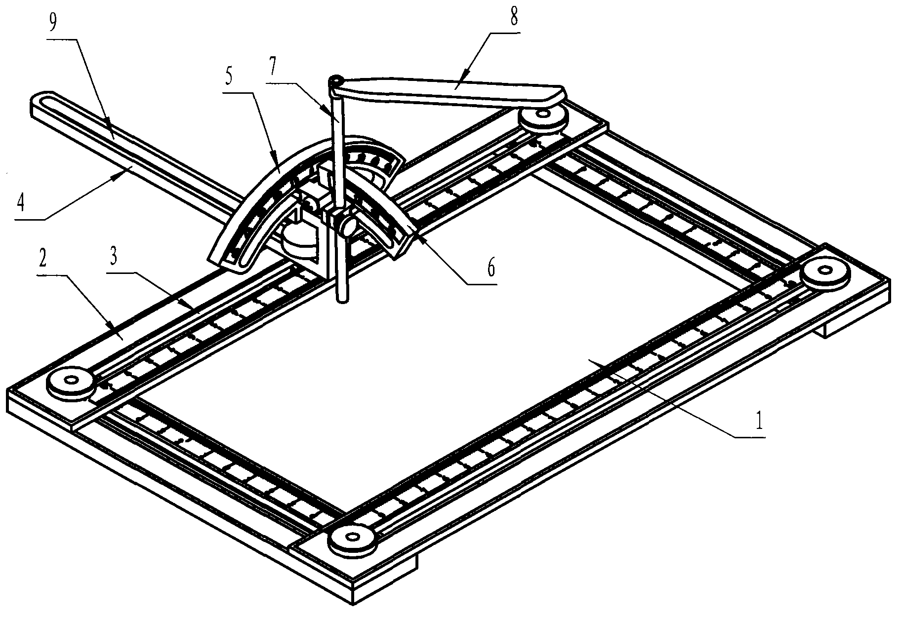
[0010] figure 1 It is a structural diagram of the positioning device for lumbosacral percutaneous pedicle screws. Two long strips and two short strips with guide grooves are connected with bolts and nuts through the slots to form a rectangular frame 1, and each long strip is installed with 2 One adjustment device (only one of them is drawn in the figure), each long strip (short strip) can translate along the guide grooves on its adjacent two short strips (long strips), two long strips and two short strips There are scale marks on the guide grooves, which are used to adjust the longitudinal translation distance of the adjusting device.

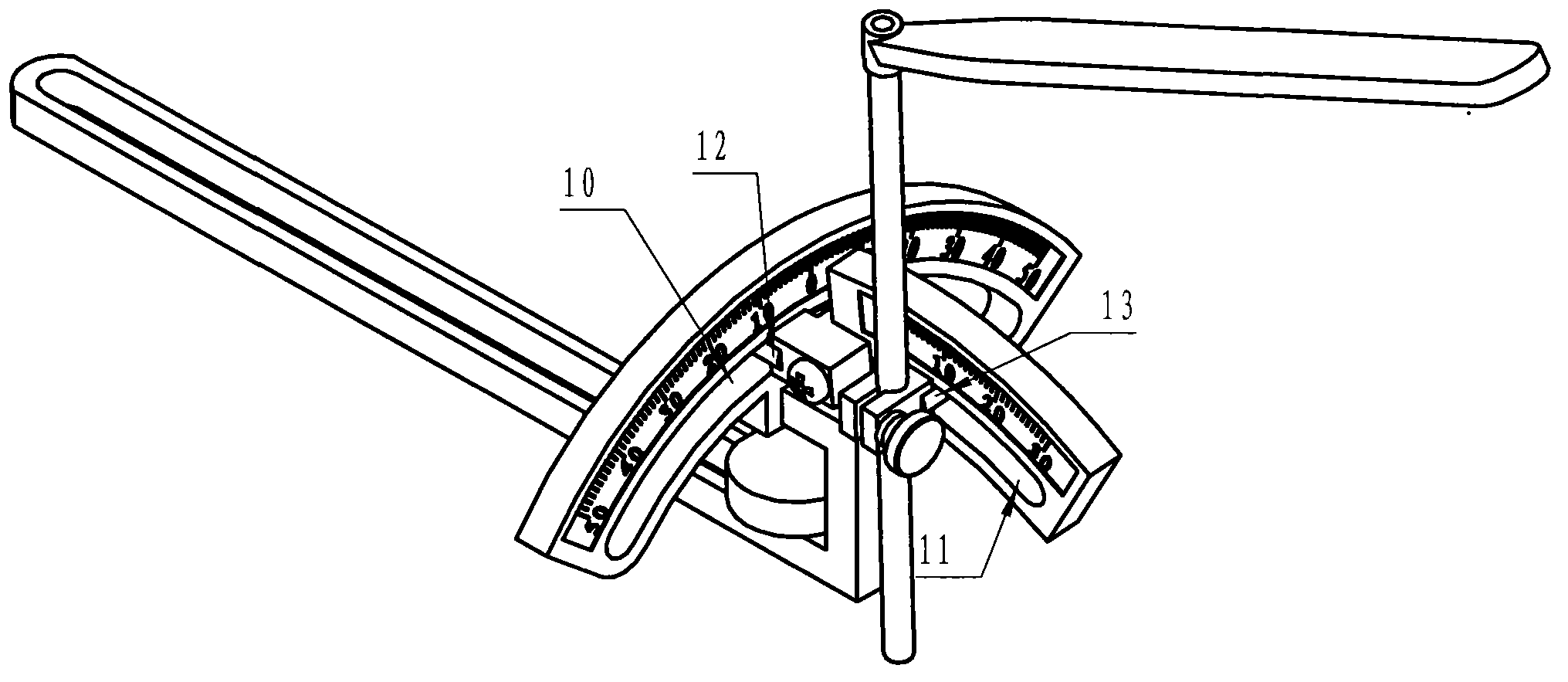
[0011] figure 2 It is a structural diagram of the adjustment device in the positioner. The adjustment device includes an adjustment rod 4, a large-angle disc 5 and a small-angle disc 6. The adjustment rod 4 with the guide groove II9 is ​​installed on the guide groove I3 of the strip 2 through screws, and the guide groove II9 is ​​provided wi...


PUM


Abstract

The invention discloses a lumbosacral vertebrae percutaneous pedicle screw placement positioner which is used for determining pedicle puncture points according to imaging data of a patient, adjusting puncture paths in a three-dimensional manner and positioning multiple pedicles once. The positioner comprises a rectangular frame formed by connection of two long strips provided with guiding grooves and two short strips provided with guiding grooves, wherein each long strip or each short strip can move horizontally along the guiding grooves in the two adjacent short strips or along the guiding grooves in the two adjacent long strips; an adjusting rod provided with a guiding groove is mounted on one long strip, can move transversely along the guiding groove in the long strip and can also move longitudinally along the guiding groove of the adjusting rod; a large-angle plate provided with an arc-shaped guiding groove I is connected with one end of the adjusting rod, a sliding block I is arranged on the arc-shaped guiding groove I to be connected with a small-angle plate provided with an arc-shaped guiding groove II; the small-angle plate can rotate along the arc-shaped guiding groove I of the large-angle plate; a sliding block II is arranged on the arc-shaped guiding groove II of the small-angle plate to be connected with a guiding pipe; the guiding pipe can rotate along the arc-shaped guiding groove II of the small-angle plate and is used for guiding in puncture screws.

Description

technical field [0001] The invention relates to a medical device, in particular to a positioning device for lumbosacral percutaneous pedicle screw placement. Background technique [0002] The technique of percutaneous external pedicle fixation began in 1977. External spinal fixation (ESSF) was applied to patients with spinal fractures and achieved good clinical results. In recent years, especially with the development of minimally invasive spinal surgery, percutaneous pedicle screw technology has become the basic technical means of minimally invasive spine surgery (MMISS, minimally invasive spine surgery), and has been gradually applied to the treatment of spinal fractures and spondylolisthesis. Osteoporosis, percutaneous vertebroplasty and kyphoplasty, lumbar instability, diagnosis or treatment of discogenic diseases. However, the traditional percutaneous puncture and pedicle screw placement have many limitations and disadvantages. For example, the operation often requires...

Claims


Application Information

Patent Timeline
Patent Type & Authority Applications(China)
IPC IPC(8): A61B17/90A61B17/70
CPCA61B17/70A61B17/90
Inventor 刘瑾问肃生王国强郭虎兵王素霞
Owner 刘瑾
Why Eureka
Try Eureka