A force line measurement angle positioning device for osteotomy around the knee joint

An angle positioning and positioning device technology, applied in application, bone drill guidance, medical science, etc., can solve the problems of increasing the dose of patients and surgeons, increasing the number of surgeons, fixing non-absolute firmness, etc., and reducing the number of perspectives and radiation quantity, improve the safety of surgery, and ensure the effect of accurate implementation

Active Publication Date: 2020-04-28
FIRST HOSPITAL AFFILIATED TO GENERAL HOSPITAL OF PLA
View PDF1 Cites 0 Cited by
  • Summary
  • Abstract
  • Description
  • Claims
  • Application Information

AI Technical Summary

Problems solved by technology

Since the doctor holds the limbs or metal rods by hand, absolute stability cannot be guaranteed, which affects the accuracy of measurement, and multiple X-ray perspectives will greatly prolong the operation time and affect the safety of patients.
In addition, the X-ray fluoroscopy process will greatly increase the dose of radiation received by patients and surgeons, affecting their health
[0005] However, there is no corresponding device in the prior art to assist in these operations. An invention patent is currently being applied for, with the application number 201710142181.5, a force line locator for high tibial osteotomy, which can solve the problem according to the description in the manual. In the existing high tibial osteotomy, the doctor needs to hold the line of force measuring piece for positioning work, which affects the accuracy of the high tibial osteotomy, and increases the radiation dose received by the surgeon and affects the health of the doctor.
However, the description does not mention how to control the neutral position of the lower limbs, so a doctor is still needed to assist in controlling the external rotation of the lower limbs during the operation
In addition, the fixation between the device and the limbs is not absolutely firm, and the limbs need to be repositioned each time after the operation, which is cumbersome to operate, and the positioner is only used for the lower limbs, and has no other derivative functions, so the scope of application is limited

Method used


Image

  • A force line measurement angle positioning device for osteotomy around the knee joint
  • A force line measurement angle positioning device for osteotomy around the knee joint
  • A force line measurement angle positioning device for osteotomy around the knee joint

Examples


Embodiment 1

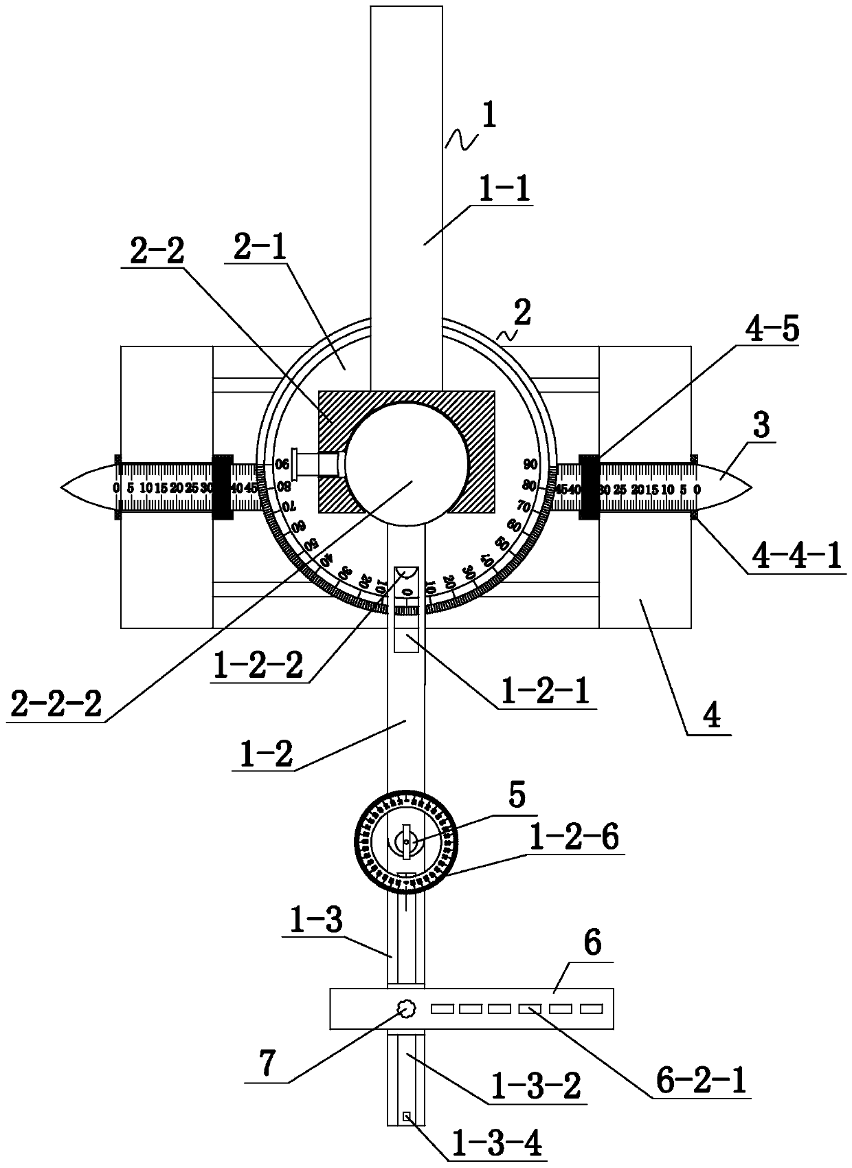
[0066] figure 1 It is a schematic diagram of the structure of the force line measuring angle positioning device used for osteotomy around the knee joint. Such as figure 1 As shown, a force line measurement angle positioning device for osteotomy around the knee joint, the positioning device includes an angle force line measurement rod 1 , a fixation assembly 2 , a support pin 3 and a splint support 4 .

[0067] The angleable force line measuring rod 1 includes a fixed rod 1-1, a first movable rod 1-2 and a second movable rod 1-3. One surface of the fixed assembly 2 is connected with one end of the fixed rod 1-1, and the opposite surface of the fixed rod 1-1 and the fixed assembly 2 on the fixed assembly 2 is movably connected with one end of the first movable rod 1-2. The other end of the movable rod 1-2 is pivotally connected to the second movable rod 1-3 through the pivot shaft 5 . The second movable rod 1-3 can swing horizontally relative to the first movable rod 1-2, and...

Embodiment 2

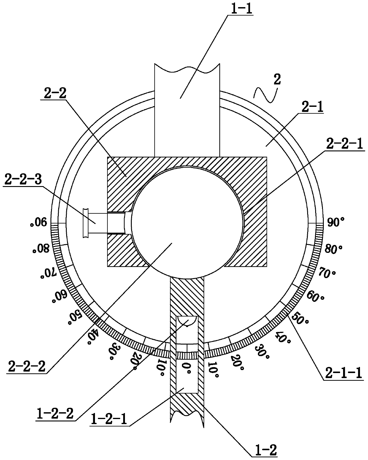
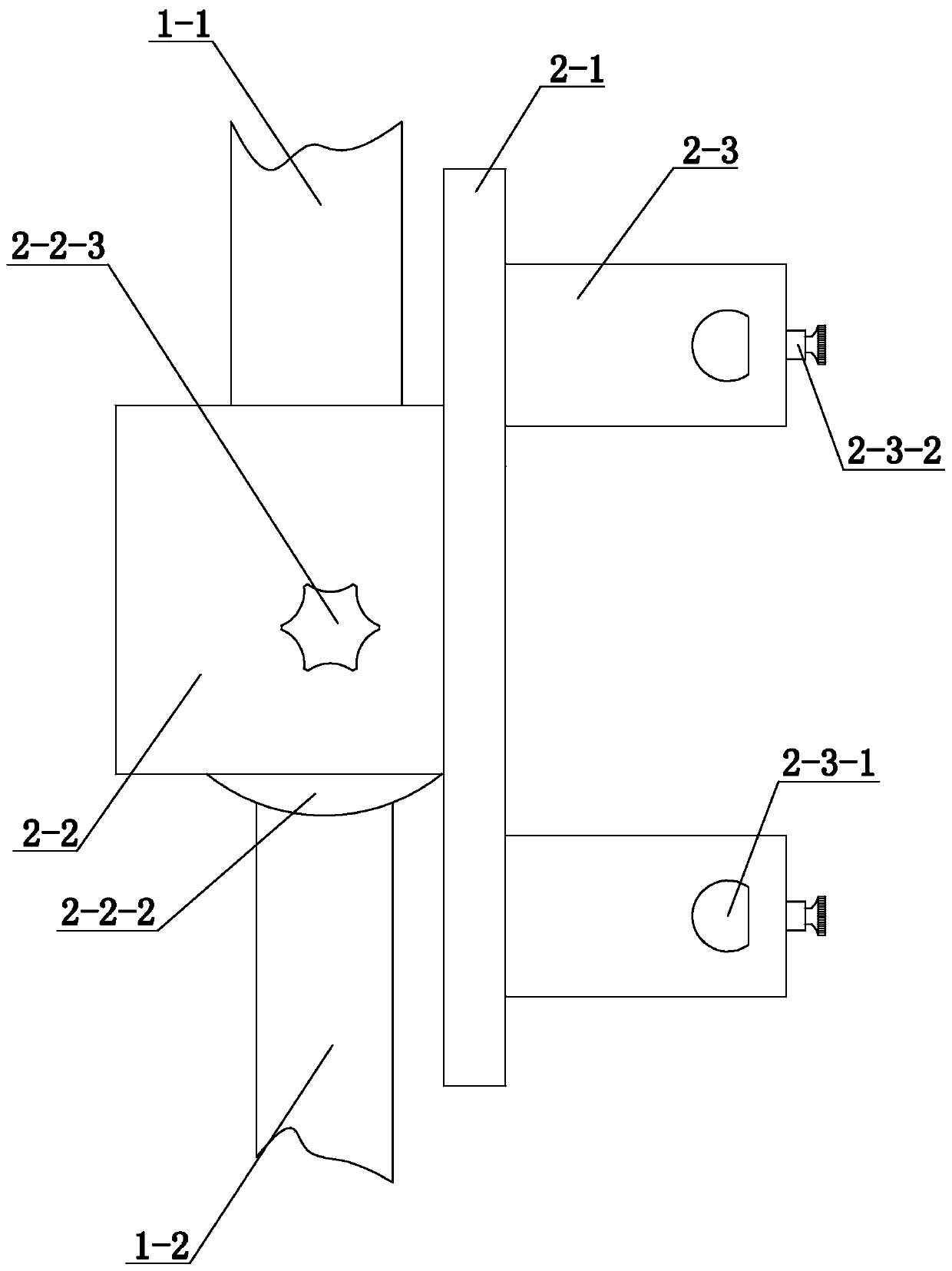
[0084] Embodiment 2 On the basis of Embodiment 1, a more preferred structure of force line measurement angle positioning device for osteotomy around the knee joint is provided, such as figure 2 and image 3 shown. Specifically, Embodiment 2 further defines that the fixing assembly 2 includes a base 2-1 and a fixing platform 2-2 connected to the upper surface of the base 2-1.

[0085] The fixed table 2-2 is provided with a spherical crown-shaped cavity 2-2-1, and the cavity 2-2-1 runs through the connection surface between the first movable rod 1-2 and the fixed component 2, and is located in the cavity on the penetration surface. The maximum pitch of the notches of the cavity 2-2-1 is smaller than the maximum diameter of the cavity 2-2-1. The plane of the cavity 2-2-1 is parallel to the base 2-1, and is attached to the base 2-1.

[0086] The cavity 2-2-1 is provided with a rotary block 2-2-2 that cooperates with the cavity 2-2-1 and can rotate horizontally. The rotary bloc...

Embodiment 3

[0093] Embodiment 3 On the basis of Embodiment 1 or Embodiment 2, a more preferred structure of force line measurement angle positioning device for osteotomy around the knee joint is provided, such as Figure 4 , Figure 6 and Figure 7 shown. Specifically, this embodiment 3 further defines that the first movable rod 1-2 is provided with a threaded through hole 1-2-3 matched with the pivot shaft 5 . The end surface of the first movable rod 1-2 close to the end of the second movable rod 1-3 is recessed with a pivotal cavity 1-2-4 along the axial direction, and the pivotal cavity 1-2-4 runs through the second movable rod along the horizontal direction. A movable rod 1-2, the pivoting cavity 1-2-4 communicates with the threaded through hole 1-2-3. A pit 1-2-5 is provided on the inner wall of the pivotal cavity 1-2-4 close to the end surface.

[0094] One end of the second movable rod 1-3 is provided with a pivotal projection 1-3-1 that cooperates with the pivotal cavity 1-2-4...


PUM


Abstract

The invention provides a positioning device for the force line measuring angle of an osteotomy around a knee. The positioning device comprises an angled force line measuring rod, a fixing assembly, asupporting needle and clamping board bases; the angled force line measuring rod comprises a fixing rod, a first movable rod and a second movable rod; one surface of the fixing assembly is connected with one end of the fixing rod, the portion, located on the opposite surface of the connected surface of the fixing rod and the fixing assembly, on the fixing assembly is movably connected with one endof the first movable rod, and the other end of the first movable rod is pivoted on the second movable rod through a pivoting shaft; the supporting needle penetrates a thighbone or shin bone of a lowerlimb of a human body, and the two ends of the supporting needle are fixed onto the clamping board bases; the fixing assembly is located above the lower limb and movably connected with the clamping board bases. The device has the advantages that a product is simple to operate, convenient to use, stable and reliable; surgical time is shortened, the precision of osteotomy orthopaedics is improved, and the number of times of fluoroscopy and the radiant quantity are greatly reduced, so that it is avoided that the patient and doctors receive too much radiation, so that physical health is affected.

Description

technical field [0001] The invention belongs to the technical field of medical devices, in particular to a force line measuring angle positioning device for osteotomy around the knee joint. Background technique [0002] Clinically, patients suffering from knee pain are more likely to have early osteoarthritis accompanied by varus deformity of the knee joint. Due to congenital or acquired factors, the proximal tibial articular surface or distal femoral articular surface is varus relative to normal people, resulting in varus deformity of the knee joint, so that the line of force of the lower limbs, that is, the weight-bearing line, passes through the medial side of the knee joint during weight-bearing, causing The medial knee joint bears greater stress, and when it exceeds the physiological tolerance level, the joint degeneration accelerates, which further aggravates the knee joint varus, resulting in a vicious circle. The line of force of the lower limbs is the line from the...

Claims


Application Information

Patent Timeline
Patent Type & Authority Patents(China)
IPC IPC(8): A61B17/17A61B90/00
CPCA61B17/1732A61B90/06A61B2090/067
Inventor 汤俊君张建吴克俭陆海波王金昌刘亭茹
Owner FIRST HOSPITAL AFFILIATED TO GENERAL HOSPITAL OF PLA
Why Eureka
Try Eureka