a pipe bending machine

A technology of pipe bending machine and frame, applied in the directions of forming tools, feeding devices, positioning devices, etc., can solve the problems of wasting manpower, easily injuring operators, and lacking, and achieve the effect of ensuring service life

Active Publication Date: 2017-11-10
STATE GRID CORP OF CHINA +2
View PDF1 Cites 2 Cited by
  • Summary
  • Abstract
  • Description
  • Claims
  • Application Information

AI Technical Summary

Problems solved by technology

The problem with the existing pipe bending machine is that when the metal pipe is bent, due to the lack of a structure for limiting the two ends of the metal pipe, it is necessary to first clamp the metal pipe in the groove of the top bending die, and then The operator manually supports the two ends of the metal pipe so that the metal pipe moves forward together with the top bending die. In this process, manpower is wasted, and the two ends of the metal pipe are tilted to the rear side during the bending process, and it is easy to injure the operator; in addition, because the metal pipe will touch the two supporting wheels after moving forward with the top bending die for a certain distance, At this time, the metal pipe has a certain initial velocity, that is, the metal pipe will produce a certain amount of impact on the support wheel, which reduces the service life of the support wheel; in addition, the existing pipe bender can only bend "V "shaped tube or "U" shaped tube, and "V" shaped tube or "U" shaped tube that cannot be bent out of the R angle

Method used


Image

  • a pipe bending machine
  • a pipe bending machine
  • a pipe bending machine

Examples


Embodiment Construction

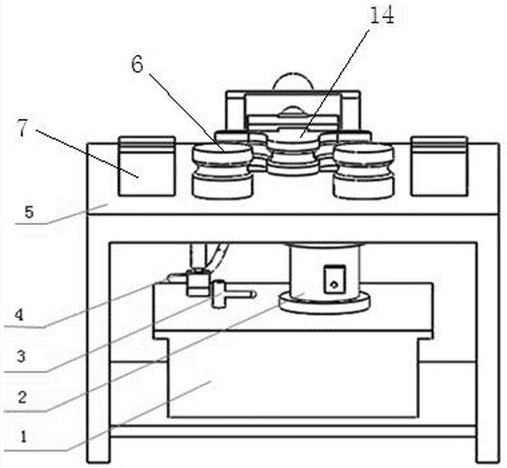
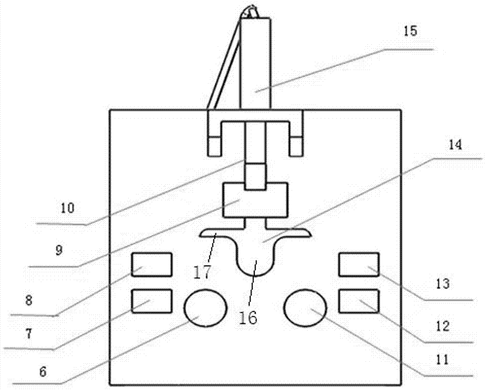
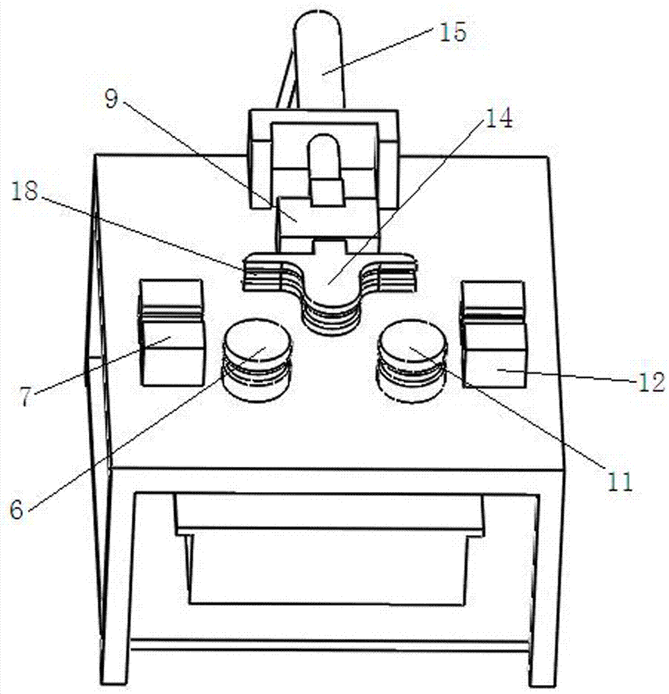
[0023] An example of a pipe bending machine Figure 1~7 Shown: including the frame, the frame includes the frame body and the upper table 5 and the lower table arranged on the frame body at intervals up and down, the frame is provided with a loading mechanism capable of outputting linear displacement motions in the front and rear directions, and the loading mechanism includes The loading oil cylinder 15 on the table, the piston rod 10 of the loading oil cylinder constitutes the power output end of the loading mechanism, the oil pump 1 driven by the motor 2 is arranged on the lower table, the oil outlet of the oil pump is connected with the oil inlet of the loading oil cylinder through the hydraulic pipeline 4 port connection. The piston rod of the loading cylinder is connected with the top bending die 14 through the connecting block 9. The connecting block moves along the front and rear directions and is assembled on the frame. The support wheel 6 and the support wheel 11 ext...


PUM


Abstract

The invention relates to a pipe bending machine, which includes a frame, on which a loading mechanism capable of outputting linear displacement in the front and rear direction is arranged, and a top bending die is connected to the power output end of the loading mechanism, and the frame is also rotatably provided with Two support wheels for cooperating with the top bending die to bend corresponding metal pipes, metal pipe limit mechanisms are arranged on the left and right sides of the two support wheels on the frame, each metal pipe limit mechanism They all have limiting passages extending straight along the left and right directions and for the corresponding ends of the metal pipes to pass through. Each limiting passage is located on the rear side of the corresponding support wheel. When the metal tube is pressed, the corresponding end of the metal tube is blocked and matched in the front and rear directions, and the channel wall is used for sliding and friction guiding cooperation in the left and right directions. The invention provides a pipe bending machine that does not need manual support by an operator and can bend an R angle during use.

Description

technical field [0001] The invention relates to a pipe bending machine. Background technique [0002] The bending and forming of metal pipes occupies an important position in various mechanical fields. For example, a lot of U-shaped bends are needed in the manufacture of gas path connection of high-voltage electrical equipment. During the installation and operation of high-voltage electrical equipment, U-shaped bends Used to compensate for pipe size changes caused by installation, thermal expansion and contraction, and operational vibration. Existing pipe benders such as the "new hydraulic pipe bender" disclosed in Chinese patent document CN201046475Y, this pipe bender includes a frame on which a hydraulic cylinder capable of outputting linear movements in the front and rear directions is housed, and the piston rod of the hydraulic cylinder is equipped with a For the top bending die, the frame is also rotatably provided with two support wheels whose rotation axes extend in ...

Claims


Application Information

Patent Timeline
Patent Type & Authority Patents(China)
IPC IPC(8): B21D7/06B21D43/00B21D37/10
Inventor 韩丽娟王路平郝留成李亚磊王晓贞李小欣
Owner STATE GRID CORP OF CHINA
Why Eureka
Try Eureka