
Vertical lathe for machining disc type workpieces and brake disc machining method

A technology for vertical lathes and brake discs, applied in metal processing machinery parts, metal processing equipment, tool clamps, etc., can solve the problems of large processing errors, reduced processing efficiency, wasted time, etc., to save clamping adjustment time, improve The effect of processing efficiency

Active Publication Date: 2014-11-12
YANTAI LUCHEN SEAWOO CNC MACHINERY
View PDF7 Cites 7 Cited by
  • Summary
  • Abstract
  • Description
  • Claims
  • Application Information

AI Technical Summary

Problems solved by technology

In this way, different lathes are used for the processing process of rough turning and semi-finishing turning. Due to repeated clamping and dismounting of workpieces, it not only wastes time and reduces processing efficiency, but also causes large processing errors due to repeated adjustments, making it difficult to adapt to large-scale workpieces. Production

Method used


Image

  • Vertical lathe for machining disc type workpieces and brake disc machining method
  • Vertical lathe for machining disc type workpieces and brake disc machining method
  • Vertical lathe for machining disc type workpieces and brake disc machining method

Examples


Embodiment Construction

[0043] The principles and features of the present invention are described below in conjunction with the accompanying drawings, and the examples given are only used to explain the present invention, and are not intended to limit the scope of the present invention.

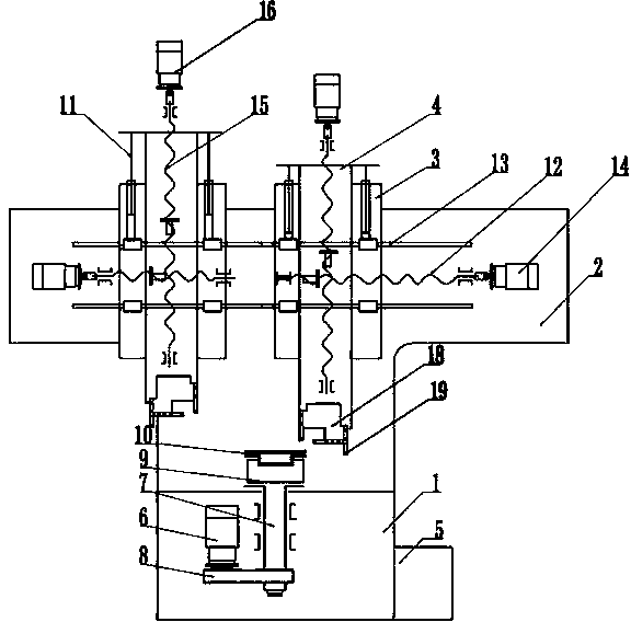
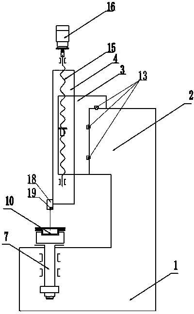
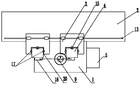
[0044] Such as Figure 1 to Figure 3 As shown, a vertical lathe for processing disc-like workpieces includes a bed 1, the bed 1 includes a base and a beam 2, and the base is provided with a workpiece rotating clamping device, and it is characterized in that the The beam 2 is provided with an X-direction linear guide rail 13, and the X-direction linear guide rail 13 is provided with left and right rams 3 that can slide horizontally. X-direction ball screw pairs 12 and X-direction servo motors 14 are arranged respectively between them, and Z-direction linear guide rails 17 are respectively provided on the left and right rams 3, and the Z-direction linear guide rails 17 are provided with vertically sliding The column ...


PUM


Abstract

The invention relates to the technical field of machining, in particular to a vertical lathe for machining disc type workpieces and a brake disc machining method. The vertical lathe comprises a lathe bed, the lathe bed comprises a base and a cross beam, a workpiece rotating clamping device is arranged on the base, and the vertical lathe is characterized in that an X-direction linear guide rail is arranged on the cross beam, left and right rams are arranged on the X-direction linear guide rail, X-direction ball screw pairs and X-direction servo motors are respectively arranged between the X-direction linear guide rail and the left and right rams, Z-direction linear guide rails are arranged on the left and right rams respectively, stand columns are arranged on the Z-direction linear guide rails, Z-direction ball lead screw pairs and Z-direction servo motors are arranged between the Z-direction linear guide rails and the stand columns, and tool mounting bases are arranged at the lower ends of the stand columns. The invention further relates to the brake disc machining method. The method comprises the steps that a left tool and a right tool respectively and independently machine different faces, the workpieces are clamped and mounted by being turned, and the other faces are machined. Compared with the prior art, the vertical lathe and the brake disc machining method have the advantages of saving clamping adjusting time and improving the machining efficiency.

Description

technical field [0001] The invention relates to the technical field of mechanical processing, in particular to a vertical lathe for processing disc workpieces, and also to a brake disc processing method. Background technique [0002] At present, for the processing of disc-like workpieces like brake discs, the traditional process is to use a lathe for rough turning first, then switch to another equipment, perform semi-finishing in the second clamping, and finally switch to finishing equipment for three times. Clamp the surface finish turning and knurling that need to be finished. In this way, different lathes are used for the processing process of rough turning and semi-finishing turning. Due to repeated clamping and dismounting of workpieces, it not only wastes time and reduces processing efficiency, but also causes large processing errors due to repeated adjustments, making it difficult to adapt to large-scale workpieces. Production. Contents of the invention [000...

Claims


Application Information

Patent Timeline
IPC IPC(8): B23B5/00B23Q5/36B23Q5/40B23Q1/01B23B1/00
CPCB23B1/00B23B5/00B23B29/26B23B2235/04B23Q1/017B23Q1/621B23Q5/28B23Q5/32B23Q2705/102
Inventor 谭松江王永峰
Owner YANTAI LUCHEN SEAWOO CNC MACHINERY
Learn More