Pneumatic tire

A pneumatic tire, tire technology, applied in tire parts, tire tread/tread pattern, transportation and packaging, etc., can solve the problems of poor ice road performance, balanced performance improvement, pattern rigidity, and friction reduction. , to achieve high drainage performance, improve snow road performance, and improve the effect of snow column shear force

Active Publication Date: 2014-11-12
SUMITOMO RUBBER IND LTD
View PDF7 Cites 3 Cited by
  • Summary
  • Abstract
  • Description
  • Claims
  • Application Information

AI Technical Summary

Problems solved by technology

However, with this method, since the ground contact area becomes smaller, the rigidity of the tread pattern and the frictional force will decrease, and there is a problem that the performance on icy roads will be deteriorated.
In this way, drainage performance and snow performance have an inverse relationship with ice performance, so it is difficult to improve all these performances in a balanced manner.

Method used


Image

  • Pneumatic tire
  • Pneumatic tire
  • Pneumatic tire

Examples


Embodiment

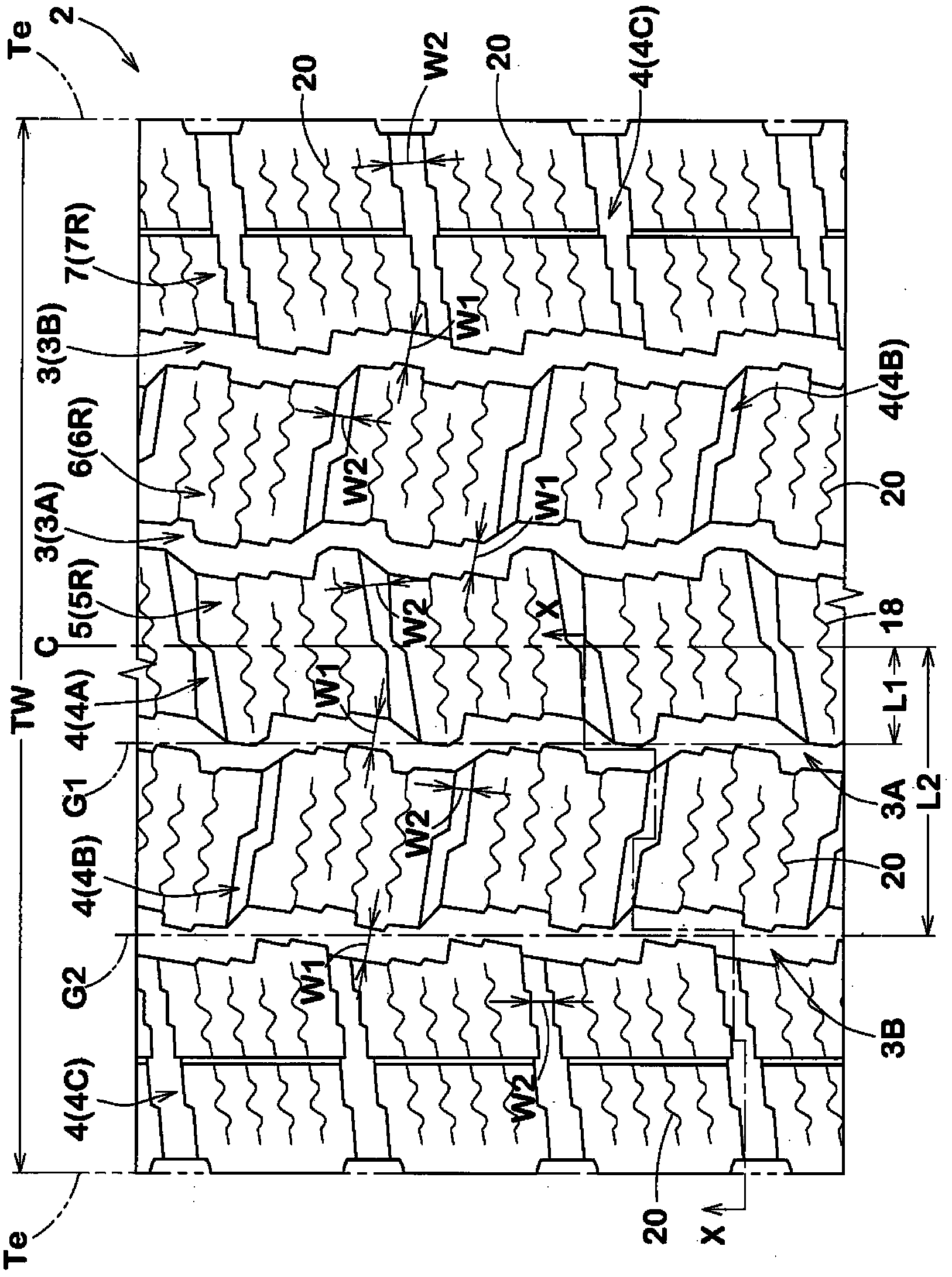
[0057] Based on the specifications in Table 1, prototypes have figure 1 The size of the basic pattern is 195 / 80R15 pneumatic tires, and the water drainage performance, ice road performance (braking force and turning performance) and snow road performance of each test tire are tested. In addition, general specifications are as follows.

[0058] Tread contact width TW: 163mm

[0059]

[0060] Groove width W1: 4.0~7.0mm

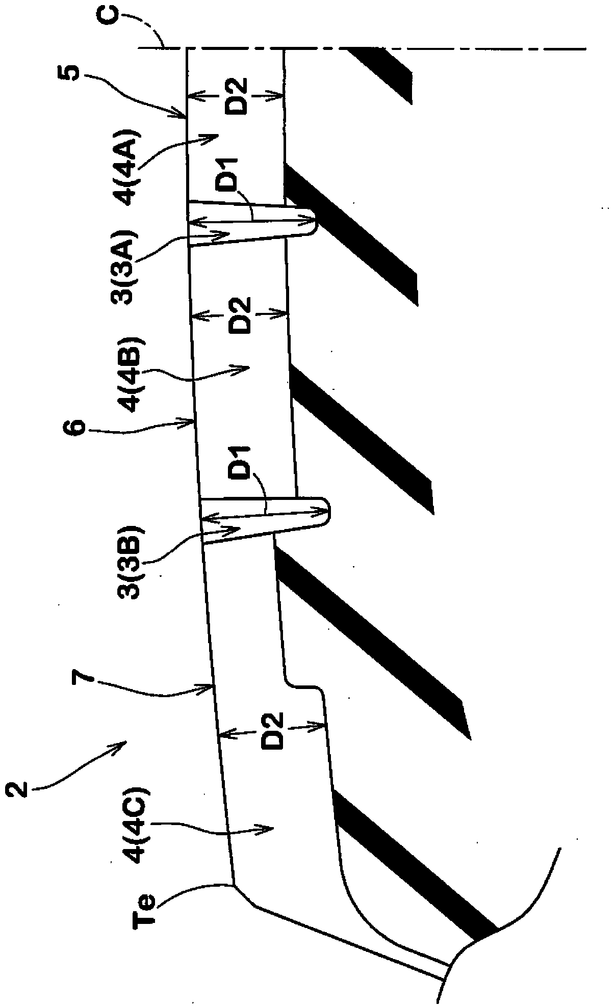
[0061] Groove depth: 12.5mm

[0062] The tire axial distance L1 / TW of the groove center line of the central main groove: 10.3%

[0063] The tire axial distance L2 / TW of the groove center line of the shoulder main groove: 28.1%

[0064]

[0065] Groove width W2: 2.0~6.0mm

[0066] Groove depth: 7.0~10.5mm

[0067] The test method is as follows.

[0068]

[0069] Under the following conditions, each test tire was mounted on all wheels of a 4-wheel drive vehicle with a displacement of 2700CC, and the vehicle was driven on a snowy road test route by a s...


PUM


Abstract

A pneumatic tire according to the invention is capable of suppressing a decrease in drainage performance and snow-covered road performance and improving icy road performance. The pneumatic tire is provided with a pair of center pattern blocks (5) divided by center main grooves (3A, 3A) and a plurality of center lateral grooves (4A, 4A) on a tread portion (2) with intervals. The center pattern blocks (5) includes: end edges on two sides of the center pattern blocks (5) in the circumferential direction of the tire, that is a pair of lateral pattern block edges (8, 8), and end edges on two sides of the center pattern blocks (5) in the axial direction of the tire, that is a pair of vertical pattern block edges (9, 9). The lateral pattern block edges (8, 8) respectively has lateral projections (10, 10) protruding outwardly in the circumferential direction of the tire, the vertical pattern block edges (9, 9) respectively has vertical projections (11, 11) protruding outwardly in the axial direction of the tire, and a ratio (Lb/La) of the maximum length (Lb) of the center pattern blocks (5) in the circumferential direction of the tire and the maximum length (La) of the center pattern blocks (5) in the axial direction of the tire is 0.80 to 1.00.

Description

technical field [0001] The present invention relates to a pneumatic tire that suppresses reductions in drainage performance and performance on snowy roads and improves performance on icy roads. Background technique [0002] In recent years, in winter pneumatic tires, chances of running on wet roads, etc. in addition to snowy roads, icy roads, etc. are also increasing. Therefore, in such winter pneumatic tires, not only snow performance and icy performance but also drainage performance are required to be improved at a high level in a balanced manner. [0003] For example, in order to improve drainage performance and snow road performance, for the purpose of smoothly draining the water film between the tread portion and the road surface and smoothly discharging snow in the main groove and lateral groove, it has been proposed to combine each of the above described A method such as increasing the groove width of the groove. However, with this method, since the ground contact a...

Claims


Application Information

Patent Timeline
Patent Type & Authority Applications(China)
IPC IPC(8): B60C11/11B60C11/12
Inventor 西胁隆志
Owner SUMITOMO RUBBER IND LTD
Why Eureka
Try Eureka