Feeding device

A technology of feeding device and mounting seat, which is applied in the direction of conveyors, mechanical conveyors, conveyor objects, etc., and can solve problems such as complex structure, high manufacturing cost, and high operating noise

Active Publication Date: 2016-09-07
苏州科昂泰材料科技有限公司
View PDF5 Cites 0 Cited by
  • Summary
  • Abstract
  • Description
  • Claims
  • Application Information

AI Technical Summary

Problems solved by technology

[0003] One is to use a manipulator to grab the jig and move it away from the horizontal conveying channel in the vertical direction, and then turn the jig grabbed by the manipulator to the vertical state through the mechanical device of the flip operation, and then move the jig vertically down to complete the wire feeding process. This method has the disadvantages of many steps in the transfer process, long time consumption, low processing efficiency of wire rods, extremely complicated structure and high manufacturing cost.
[0004] The second is to send the jig from the horizontal conveying channel to a section of vertical conveying channel after turning over, so as to dip flux or tin-plate the wire, and then turn the fixture back to the horizontal conveying channel after the operation is completed. This method also has the disadvantages of many steps in the transfer process, long time-consuming, low processing efficiency of wire rods, extremely complicated structure and high manufacturing cost.
Moreover, the jig needs to be provided with a structure that prevents it from falling away from the vertical conveying flow channel, which increases the processing difficulty of the jig and accordingly increases the manufacturing cost of the equipment.
[0005] The third is to set a movable rotating conveying channel to rotate together with the jig. This method also has the disadvantages of extremely complicated structure and high manufacturing cost; The processing difficulty of the jig is increased, which also increases the manufacturing cost of the equipment; moreover, the structure of the rotary conveying channel and the jig turned over together is huge and heavy, and it needs to use a high-power motor or a large-bore cylinder to smoothly Driving the entire structure to realize the flipping action consumes a lot of energy, and the structure is complicated, the manufacturing cost is expensive, the operation noise is loud and the response speed is slow
[0006] To sum up, the currently used mechanical device for transferring the jig loaded with the wire to be processed from the horizontal conveying flow channel to the vertical state for dipping flux or tinning operations is far from meeting the needs of today's use.

Method used


Image

  • Feeding device
  • Feeding device
  • Feeding device

Examples


Embodiment Construction

[0025] In order to describe the technical content and structural features of the present invention in detail, further description will be given below in conjunction with the implementation and accompanying drawings.

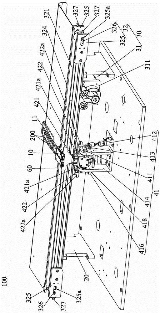
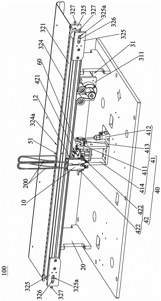
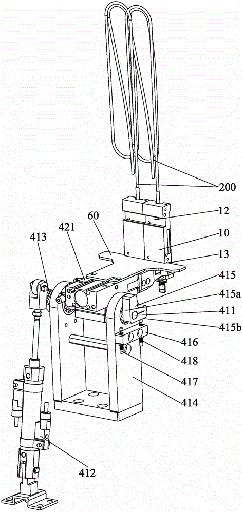
[0026] see Figure 1 to Figure 4, the feeding device 100 of the present invention comprises a jig 10, a frame 20 and a first transfer mechanism 30 and a second transfer mechanism 40 located on the frame 20, the jig 10 is used to load the workpiece 200 to be processed; the first transfer mechanism 30 includes a transfer drive assembly 31 and a load guide assembly 32 that are located on the frame 20. The load guide assembly 32 includes a load transmission member (not marked in the figure) and a guide rail 324 that are located on the frame 20 and are parallel to each other. The jig 10 is carried on the carrying transmission part and is in sliding fit with the guide rail 324. The transfer drive assembly 31 is associated with the jig 10 or the carrying transmission pa...


PUM


Abstract

The invention discloses a material feeding device, which includes a jig, a frame, a first transfer mechanism and a second transfer mechanism; the first transfer mechanism includes a transfer drive assembly and a load-bearing guide assembly arranged on the The supporting transmission part and the guide rail are parallel to each other. The fixture loaded with the workpiece is carried on the carrying transmission part and is in sliding fit with the guide rail. The transfer drive assembly is associated with the fixture or the carrying transmission part to drive the fixture along the direction parallel to the guide rail. Move; the frame is distributed with at least one clamping station along the direction parallel to the guide rail, any clamping station is correspondingly provided with a second transfer mechanism, and the second transfer mechanism includes a flipping assembly arranged on the frame and at least one clip The clamping component is connected to the flipping component, and the guide rail is provided with a avoiding part arranged along the pivoting direction of the clamping component at the clamping station and used to avoid the turning action of the jig, and the clamping component is provided with a corresponding avoiding part The auxiliary guide rail, the jig and the auxiliary guide rail are in sliding fit.

Description

technical field [0001] The invention relates to a mechanical device for conveying workpieces, in particular to a feeding device. Background technique [0002] In the field of wire rod processing, wire rods need to be processed by laser cutting, peeling, flux dipping, tinning, cutting, welding and other processes. Among them, the currently used methods of transferring the jig loaded with the wire to be processed from the horizontal conveying flow channel to the vertical state for dipping flux or tinning operations are mainly: [0003] One is to use a manipulator to grab the jig and move it away from the horizontal conveying channel in the vertical direction, and then turn the jig grabbed by the manipulator to the vertical state through the mechanical device of the flip operation, and then move the jig vertically down to complete the wire feeding process. This method has the disadvantages of many steps in the transfer process, long time consumption, low wire processing effici...

Claims


Application Information

Patent Timeline
Patent Type & Authority Patents(China)
IPC IPC(8): B65G47/90B65G47/248B65G47/24B65G35/00
Inventor 姚天金
Owner 苏州科昂泰材料科技有限公司
Why Eureka
Try Eureka