Welding fixing device for steel structural member

A technology for steel structural parts and fixing devices, applied in welding equipment, auxiliary devices, auxiliary welding equipment, etc., can solve the problems of cracking and breaking at the welding place, inconvenient steel plate welding, and reducing work efficiency, etc., to strengthen the welding effect and improve the fixing. effect, improve work efficiency

Pending Publication Date: 2022-08-05
WUHU TIANHANG TECH GRP
View PDF0 Cites 0 Cited by
  • Summary
  • Abstract
  • Description
  • Claims
  • Application Information

AI Technical Summary

Problems solved by technology

[0003] In the process of steel structure processing, it is often necessary to weld some steel plates together, but the position of the steel plates is prone to shift when the fixing device used for welding of the existing steel structure parts is used to fix the steel plates, and multiple calibrations are required to reduce the work efficiency, and the existing fixing device cannot drive the steel plate to rotate, so it is inconvenient to weld the reverse side of the steel plate, and the staff needs to reverse it, and the staff will cause the front welding part to crack and break, which is a waste of time and poor in practicability

Method used


Image

  • Welding fixing device for steel structural member
  • Welding fixing device for steel structural member

Examples


Embodiment 1

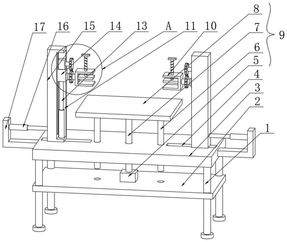
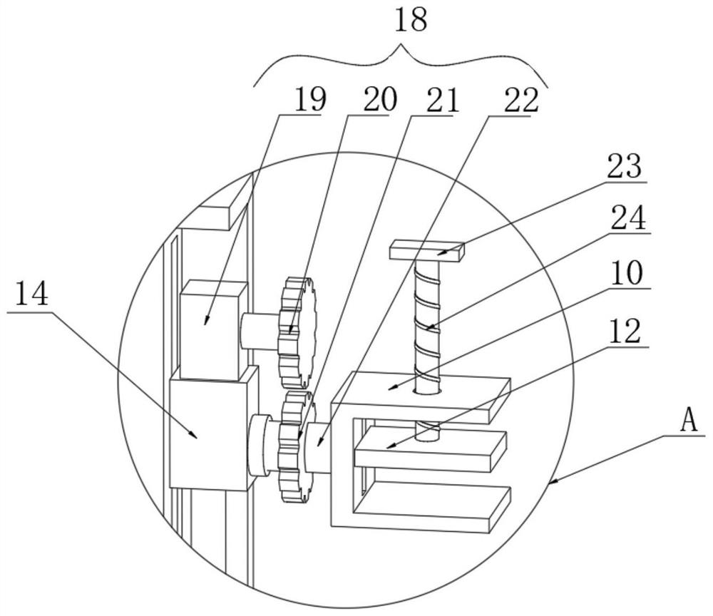
[0023] see figure 1 , the present invention provides a technical solution: a welding fixing device for a steel structure, comprising a top plate 3, four groups of support legs 1 are arranged at the bottom of the top plate 3, the four groups of support legs 1 are distributed in a rectangular array at the bottom of the top plate 3, Under the action of the leg 1, the overall fixing device is more stable. The bottom plate 2 is arranged under the top plate 3, and the placement component 9 is arranged on the top of the bottom plate 2. The placement component 9 is used to place the steel structure. There are fixed columns 15. The opposite side walls of the two sets of fixed columns 15 are provided with sliding grooves 11. The inner bottoms of the two sets of sliding grooves 11 are provided with hydraulic rods 13. The tops of the two sets of hydraulic rods 13 are provided with sliding blocks 14. The top of the sliding block 14 is provided with a rotating assembly 18 , and the opposite...

Embodiment 2

[0032] refer to figure 1 , this embodiment is different from the first embodiment in that: the placement assembly 9 includes a hydraulic cylinder 5 provided on the top of the bottom plate 2, the power output end of the hydraulic cylinder 5 is connected with a hydraulic rod 7, and a placement plate 8 is provided above the top plate 3, The top of the hydraulic rod 7 penetrates the bottom of the top plate 3 and is connected to the bottom of the placing plate 8. Under the action of the hydraulic cylinder 5, the hydraulic rod 7 is driven to move downward, and the hydraulic rod 7 drives the placing plate 8 to contact the upper surface of the top plate 3 to prevent the steel plate from turning over. When the plate 8 is placed, the steel plate is blocked.

[0033] There are limit rods 6 on the left and right sides of the bottom of the placing plate 8. The bottoms of the two sets of limit rods 6 penetrate through the top of the top plate 3 and the top of the bottom plate 2 and extend t...


PUM


Abstract

The invention discloses a welding fixing device for a steel structural part in the technical field of welding fixtures, which comprises a top plate, a bottom plate is arranged below the top plate, a placing assembly is arranged at the top of the bottom plate and is used for placing a steel structure, and fixing columns are slidably connected to the left and right sides of the top of the top plate; according to the device, two sets of steel plates are placed on the placing plate, then the positions, needing to be welded, of the two sets of steel plates are aligned, then the fixing columns are driven to move under the action of the first hydraulic rod, the steel plates are fixed through the first hydraulic rod, and the steel plates are fixed through the second hydraulic rod. According to the steel plate welding device, the fixing plate fixes the side walls, away from each other, of the two sets of steel plates, then the steel plates can be clamped under the action of the clamping plate, the rotating plate and the threaded rod, so that the positions, needing to be welded, of the two sets of steel plates cannot deviate, the fixing effect is improved, the welding effect is enhanced, and the working efficiency is improved.

Description

technical field [0001] The invention relates to the technical field of welding fixtures, in particular to a welding fixing device for steel structural parts. Background technique [0002] Steel structure is a structure composed of steel materials and is one of the main types of building structures. In the process of steel structure production and processing, different parts need to be welded, and tooling fixtures are required to fix the steel during the welding process. stable. [0003] In the process of steel structure processing, it is often necessary to weld some steel plates together. However, the position of the steel plate is easily shifted when the steel plate is fixed by the fixing device used for the welding of the existing steel structure. In addition, the existing fixing device cannot drive the steel plate to rotate, so it is inconvenient to weld the reverse side of the steel plate, and the staff needs to reverse it. SUMMARY OF THE INVENTION [0004] The purpo...

Claims


Application Information

Patent Timeline
IPC IPC(8): B23K37/04B23K37/047
CPCB23K37/0443B23K37/047Y02E10/50
Inventor 李云贵王吴俊曹成军陈霆陈海微
Owner WUHU TIANHANG TECH GRP
Why Eureka
Try Eureka