Automatic power generating and power supply system by using vehicular dive flap or deceleration strip

An automatic power generation and power supply system technology, applied in the direction of machines/engines, mechanical power generating mechanisms, mechanical equipment, etc., can solve the problems of energy waste, vehicle deceleration, etc., and achieve the effect of increasing comfort and firm and reliable structure

Inactive Publication Date: 2006-12-20
樊维亚
View PDF0 Cites 29 Cited by
  • Summary
  • Abstract
  • Description
  • Claims
  • Application Information

AI Technical Summary

Problems solved by technology

Therefore, although the traditional speed brakes or speed bumps can serve the purpose of decelerating the car, it brings some unnecessary waste of energy.

Method used


Image

  • Automatic power generating and power supply system by using vehicular dive flap or deceleration strip
  • Automatic power generating and power supply system by using vehicular dive flap or deceleration strip

Examples


Embodiment Construction

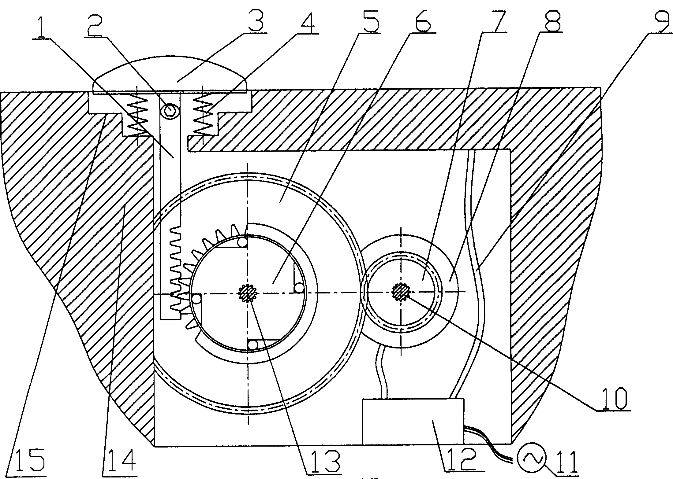
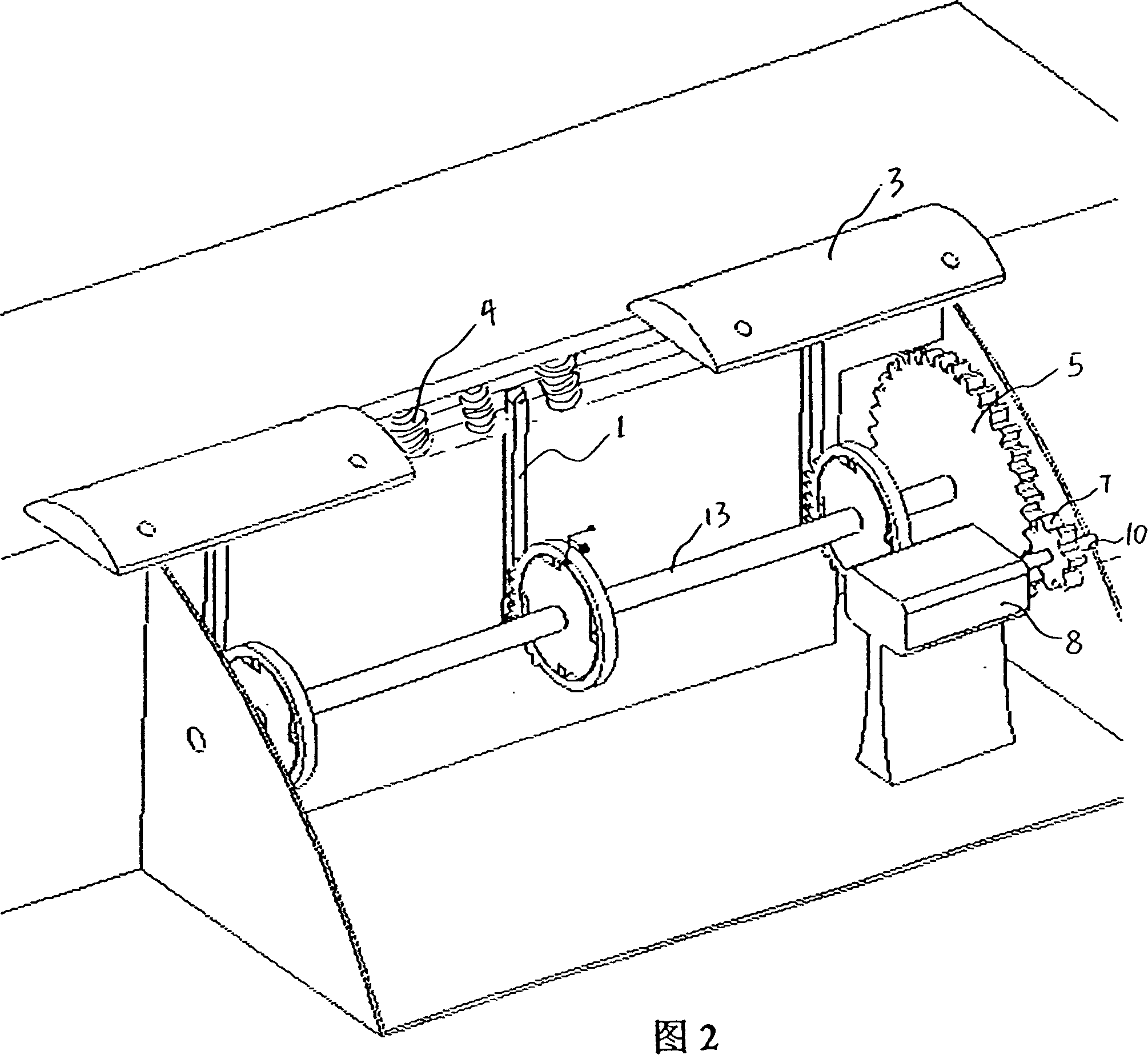
[0020] The specific structure and implementation mode of the present invention can refer to accompanying drawing. figure 1 Middle: 1 is gear rod, 2 is hinge, 3 is deceleration plate or deceleration belt, 4 is nonlinear spring, 5 is large gear, 6 is ratchet, 7 is pinion, 8 is generator, 9 is power supply output end, 10 Is the motor shaft, 11 is the terminal connected to the mains network, 12 is the controller and the storage battery, 13 is the fixed shaft of the ratchet and the large gear, 14 is the housing, and 15 is the limit boss. The speed brake or speed bump 3 is embedded in the upper chamber of the housing 14, and the upper chamber has a structure of limiting boss 15, so that the speed brake or speed bump 3 is limited downwards at the boss. The lower end surface of the fixed spring 4 is lower than the boss. The upper end of gear rod 1 is connected with the bottom end of deceleration plate or deceleration belt 3 through hinge 2. A toothed rack or transmission gear sector...


PUM


Abstract

The invention relates to an automatic generating system which uses the vehicle decelerating plate or decelerating belt, wherein it comprises: a decelerating plate or decelerating belt, non-liner spring, transmission device, generator and a frame; said transmission device comprises a tooth rod whose top via hinge and decelerating plate or belt to realize movable connection, the tooth bar at the end of tooth rod, a ratchet meshed with tooth bar, the gear couple coaxially arranged with ratchet, and a generator; the upper part of frame is the decelerating plate or the decelerating belt embed chamber; the middle part is the tooth rod motion guide chamber; and the lower part is the generating accumulating chamber. The invention can effectively utilize the energy consumed by decelerating plate, to generate electricity. And the flexible system is mounted under the decelerating plate, to improve the safety and service life of vehicle.

Description

technical field [0001] The invention relates to an automatic power generation and power supply system which utilizes the kinetic energy of depressing the speed brake or the speed bump when the vehicle passes the speed brake or the speed bump to generate electricity, and stores and supplies electric energy at the same time, which belongs to the clean energy generation and supply system. Background technique [0002] At present, in many public places such as shopping malls, communities, schools, entrances and exits of stations, large parking lots, expressway toll offices, etc., in order to reduce traffic accidents and limit vehicle speed, most roads use speed bumps or speed belts to reduce the speed of vehicles. driving speed. Ordinary speed brakes or speed bumps are fixed on the road. Although the vehicle can achieve the purpose of deceleration when it crosses the speed brake or speed bump, it consumes some extra energy. Taking a car weighing about 2,000kg as an example, und...

Claims


Application Information

Patent Timeline
Patent Type & Authority Applications(China)
IPC IPC(8): F03G7/08
CPCF03G7/08
Inventor 樊维亚李良霞于立国
Owner 樊维亚
Why Eureka
Try Eureka