Supercharge Your Innovation With Domain-Expert AI Agents!

Transmission coupler

A coupling and clamping ring technology, applied in the mechanical field, can solve problems such as inconvenient installation, poor transmission effect, complex structure, etc., and achieve the effect of convenient installation, compact structure and good transmission effect

Inactive Publication Date: 2014-11-19
WUXI AOYUTE NEW TECH DEV
View PDF5 Cites 0 Cited by
  • Summary
  • Abstract
  • Description
  • Claims
  • Application Information

AI Technical Summary

Problems solved by technology

[0002] As we all know, the transmission coupling is to transmit the power of the first shaft to the second shaft, but the current transmission coupling used for the transmission shaft of the same shaft diameter has a complicated structure, inconvenient installation, and poor transmission effect

Method used


Image

  • Transmission coupler

Examples


Embodiment Construction

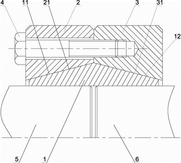
[0011] Such as figure 1 As shown, a transmission coupling of the present invention is mainly composed of a bushing 1, a first clamping ring 2 and a second clamping ring 3. The bushing 1 is in the shape of a ring, and its outer surface is processed into a symmetrical arrangement. The first tapered surface 11 and the second tapered surface 12, the tapered surface of the inner tapered hole 21 of the first clamping ring 2 fits with the first tapered surface 11 of the bushing 1, and the tapered surface of the second clamping ring 3 The tapered surface of the inner tapered hole 31 is in contact with the second tapered surface 12 of the bushing 1 , and the first clamping ring 2 and the second clamping ring 3 are tightly connected by bolts 4 .

[0012] The first clamping ring 2 is processed with a through hole along the axial direction near the outer end.

[0013] The end surface of the second clamping ring 3 opposite to the first clamping ring 2 is processed with threaded holes.

...


PUM


Abstract

The invention discloses a transmission coupler. The transmission coupler mainly comprises a lining, a first clamping ring and a second clamping ring. The lining is of a circular ring shape. The outer surface of the lining is machined into a first conical surface and a second conical surface, wherein the first conical surface and the second conical surface are symmetrical. A conical surface of an inner cone hole of the first clamping ring is attached to the first conical surface of the lining. A conical surface of an inner cone hole of the second clamping ring is attached to the second conical surface of the lining. The first clamping ring and the second clamping ring are connected in a fastened mode through a bolt. The transmission coupler is used for connecting two shafts with the same diameter quite conveniently and reliably, is good in transmission effect, and has the advantages of being compact in structure, low in cost, easy to manufacture and convenient to install.

Description

technical field [0001] The invention belongs to the technical field of machinery, in particular to a transmission shaft coupling. Background technique [0002] As we all know, the transmission coupling transmits the power of the first shaft to the second shaft, but the current transmission coupling used for the transmission shaft with the same shaft diameter has a complicated structure, inconvenient installation, and poor transmission effect. Contents of the invention [0003] The problem to be solved by the present invention is to overcome the deficiencies in the background technology and provide a transmission coupling. This transmission coupling adopts a special structure, which has large transmission torque and good transmission effect. [0004] In order to solve the above problems, the present invention takes the following technical solutions: [0005] A transmission coupling of the present invention is mainly composed of a bushing, a first clamping ring and a second...

Claims


Application Information

Patent Timeline
Patent Type & Authority Applications(China)
IPC IPC(8): F16D1/033
Inventor 张鹏其他发明人请求不公开姓名
Owner WUXI AOYUTE NEW TECH DEV
Features
  • R&D
  • Intellectual Property
  • Life Sciences
  • Materials
  • Tech Scout
  • Unparalleled Data Quality
  • Higher Quality Content
  • 60% Fewer Hallucinations
Learn More