A microchannel heat exchanger with staggered inner groove structure and its manufacturing method

A technology of micro-channel heat exchanger and manufacturing method, applied in the direction of heat exchanger type, indirect heat exchanger, heat exchange equipment, etc., to achieve the effect of increasing heat transfer area, enhancing heat transfer, and enhancing boiling heat transfer

Active Publication Date: 2016-05-04
XIAMEN UNIV
View PDF9 Cites 0 Cited by
  • Summary
  • Abstract
  • Description
  • Claims
  • Application Information

AI Technical Summary

Problems solved by technology

However, the enhanced heat transfer of microchannel heat exchangers with inner groove structures has not been reported yet.

Method used


Image

  • A microchannel heat exchanger with staggered inner groove structure and its manufacturing method
  • A microchannel heat exchanger with staggered inner groove structure and its manufacturing method
  • A microchannel heat exchanger with staggered inner groove structure and its manufacturing method

Examples


Embodiment Construction

[0031] The present invention will be further described below through specific embodiments.

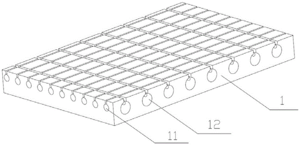
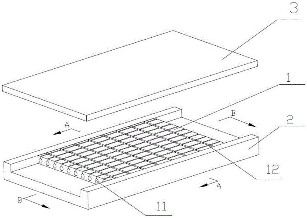
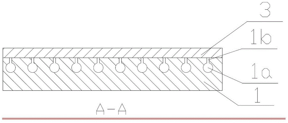
[0032] A microchannel heat exchanger with staggered inner groove microchannel structure, such as Figure 1 to Figure 4 As shown, it includes a metal microchannel substrate 1 , inlet and outlet channel chambers 2 and heat-resistant glass 3 . The substrate 1 includes a plurality of longitudinal microchannels 11 parallel to the flow direction of the coolant and spaced apart from each other, and a plurality of transverse microchannels 12 perpendicular to the longitudinal microchannels 11 and spaced apart from each other. The longitudinal microchannels 11 and the transverse microchannels 12 form a criss-cross microchannel array. Both the longitudinal microchannel 11 and the transverse microchannel 12 are in the shape of inner grooves, which include an embedded groove body 1a located inside the substrate 1 and a slit 1b forming the opening of the substrate 1, the embedded groove body 1a and...


PUM

PropertyMeasurementUnit
diameteraaaaaaaaaa
diameteraaaaaaaaaa
depthaaaaaaaaaa

Abstract

The invention discloses a micro-channel heat exchanger with a staggered inner groove structure and a manufacturing method of the micro-channel heat exchanger. The micro-channel heat exchanger with the staggered inner groove structure comprises a metal micro-channel substrate, wherein the metal micro-channel substrate comprises a plurality of longitudinal micro-channels and a plurality of transverse micro-channels; the longitudinal micro-channels are arrayed in parallel along a cooling liquid flowing direction; the transverse micro-channels are perpendicular to the longitudinal micro-channels; the longitudinal micro-channels and the transverse micro-channels are arranged at intervals; the micro-channels are in the shape of an inner groove; each micro-channel comprises an inlaid groove body and a slit; the inlaid groove bodies are positioned in the substrate; an opening position of the substrate is formed by the slits; and each inlaid groove body is connected with the corresponding slit. When the micro-channel heat exchanger is manufactured, the longitudinal inner groove micro-channels are machined along the liquid flowing direction in a linear cutting manner; after a workpiece rotates at an angle of 90 degrees, the transverse inner grooves are machined in a linear cutting manner, so that a crisscross micro-channel array is obtained; and the micro-channels are packaged by heat-resistant glass, and the staggered inner groove micro-channel heat exchanger is formed. The manufacturing process is simple and is low in cost; a thermal boundary layer is developed intermittently, and the heat transfer area is increased; and moreover, by the inner groove structure, boiling nucleation can be remarkably facilitated, and boiling heat transfer is strengthened, so that heat transfer is strengthened integrally.

Description

Technical field: [0001] The invention relates to a heat exchanger for heat transfer, in particular to a microchannel heat exchanger with a staggered inner groove structure and a manufacturing method thereof. Background technique: [0002] In recent years, with the continuous improvement of the integration of electronic products, the power of electronic equipment has increased sharply, while the physical size has become smaller and smaller, the heat flux per unit area has been greatly increased, and the problem of product failure caused by high heat flux has become increasingly serious. The use of microchannel heat exchangers to achieve high-efficiency liquid cooling is considered to be an effective solution to the problem of high heat flux. Ordinary microchannel heat exchangers process a number of open microchannel structures such as rectangles, triangles, and trapezoids arranged in parallel on a metal or silicon substrate, and are coupled and encapsulated by a cover plate t...

Claims


Application Information

Patent Timeline
Patent Type & Authority Patents(China)
IPC IPC(8): F28D1/00F28F13/00B23P15/26
Inventor 邓大祥秦嘉逸万伟凌伟淞张军鹏周伟秦利锋
Owner XIAMEN UNIV
Why Eureka
Try Eureka