Resonant liquid densitometer driver

A density meter and resonant technology, applied in the driving field of resonant liquid density meters, can solve the problems of low measurement accuracy and achieve the effect of high precision and convenient use

Inactive Publication Date: 2014-11-19
范明军
View PDF7 Cites 2 Cited by
  • Summary
  • Abstract
  • Description
  • Claims
  • Application Information

AI Technical Summary

Problems solved by technology

[0003] The resonant tube densitometer in the prior art requires a strong drive to obtain the required resonant frequency of the vibrating tube due to the vibration of the vibrating tube, and the measurement accuracy is low

Method used


Image

  • Resonant liquid densitometer driver
  • Resonant liquid densitometer driver

Examples


specific Embodiment

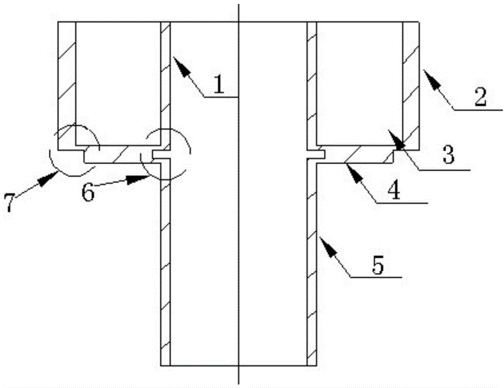
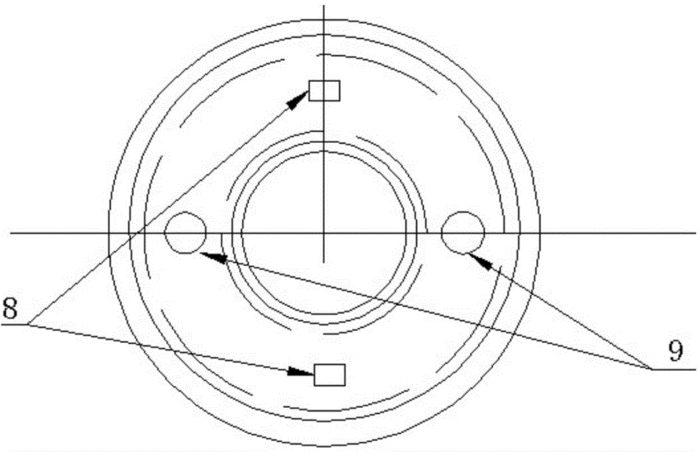
[0020] Such as figure 1 , figure 2 As shown, the inner wall between the vibration tube and the circuit protection inner tube is processed with a rectangular groove, and the outer edge of the lower surface of the bottom wall of the excitation / vibration pickup cavity is provided with a concave step. The drive acts directly on the metal (the bottom wall of the excitation / pickup cavity) perpendicular to the vibration tube. Two vibration-exciting parts are placed on the metal perpendicular to the vibration tube at an angle of 180 degrees, and the angle between the vibration-pickup part and the vibration-exciting part is 90 degrees. The circuit protects the vibration excitation / pickup cavity formed by the inner tube and the bottom wall, which is completely isolated from the liquid.


PUM


Abstract

The invention discloses a resonant liquid densitometer driver, and the resonant liquid densitometer driver comprises a vibration exciter / vibration pickup cavity including a circuit protection outer tube, a circuit protection inner tube and a bottom wall; the lower part of the circuit protection inner tube is connected with a vibration tube, the inner wall between the vibration tube and the circuit protection inner tube is processed with a rectangular groove, and vibration exciter components and vibration pickup components are fixed on the bottom wall. The bottom wall is vertical to the vibration tube, the numbers of the vibration exciter components and the vibration pickup components are respectively two, and the vibration exciter components and the vibration pickup components are uniformly arranged along the circumference of the bottom wall, and are mutually spaced. The outer edge of the lower surface of the bottom wall is provided with concave steps. The circuit protection inner tube and the vibration tube are concentric and same in diameter and wall thickness. When the vibration exciter / vibration pickup cavity drives, the vibration of the vibration tube can be very easy to perform for measuring of resonant frequency of the vibration tube, and the density of a to-be-measured liquid can be obtained.

Description

technical field [0001] The invention relates to a resonant cylinder density meter, in particular to a drive for a resonant liquid density meter. Background technique [0002] There are many forms of resonant densitometers, among which the resonant cylinder densitometer is the main form. [0003] The resonant tube densitometer in the prior art requires a strong drive to obtain the required resonant frequency of the vibrating tube due to the vibration of the vibrating tube, and the measurement accuracy is low. Contents of the invention [0004] The purpose of the present invention is to provide an easy-to-drive, high-precision drive for a resonant liquid density meter. [0005] The purpose of the present invention is achieved through the following technical solutions: [0006] The drive of the resonant liquid density meter of the present invention includes an excitation / vibration pickup chamber composed of a circuit protection outer tube, a circuit protection inner tube an...

Claims


Application Information

Patent Timeline
Patent Type & Authority Applications(China)
IPC IPC(8): G01N9/00
Inventor 范明军温宝博王磊徐顺福尹永亮
Owner 范明军
Why Eureka
Try Eureka