
Camera distortion calibration method on basis of multiple constraints

A distortion calibration and camera technology, applied in the field of distortion correction, can solve problems such as large amount of calculation, difficult convergence, inaccurate solution, etc., and achieve the effect of avoiding redundancy and optimizing camera parameters reasonably

Inactive Publication Date: 2014-11-19
DALIAN UNIV OF TECH
View PDF2 Cites 7 Cited by
  • Summary
  • Abstract
  • Description
  • Claims
  • Application Information

AI Technical Summary

Problems solved by technology

[0005] The technical problem to be solved by the present invention is to overcome the deficiencies of the prior art. For the forging site, the traditional method for obtaining the distortion coefficient in the calibration process is not easy to converge, the amount of calculation is large, and it cannot even provide enough constraints so that the solution is not correct. In order to solve the problem of accuracy and other problems, a distortion correction method based on pure translation two-view geometry is invented, and the distortion coefficient is solved separately. Better parameter estimation value; according to the present invention, the distortion correction of feature points on all acquired images can eliminate the influence of distortion on the estimation of the basic matrix and the calibration of camera parameters, and is suitable for on-site calibration of cameras in large forging size measurement systems

Method used


Image

  • Camera distortion calibration method on basis of multiple constraints
  • Camera distortion calibration method on basis of multiple constraints
  • Camera distortion calibration method on basis of multiple constraints

Examples


Embodiment Construction

[0038] The specific embodiment of the present invention will be further described in detail below in conjunction with accompanying drawings and technical solutions;

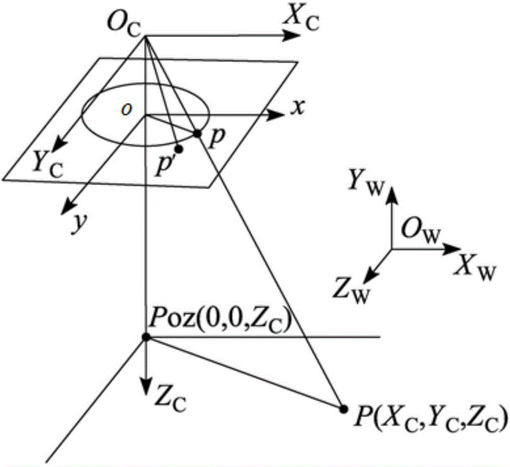
[0039] in the attached figure 1 In, O C x C Y C Z C is the camera coordinate system, O W x W Y W Z W is the world coordinate system, oxy is the object point coordinate system, O C is the optical center, and P is the object point. The lens distortion of the camera causes the light to shift slightly and produces aberrations, which are called optical distortion errors, causing the image point position of the object point P to shift from the ideal imaging point p of the object point P described by the linear model to the actual imaging point p′, Such as figure 1 shown. The pixel coordinates of the image are (u, v) and (u′, v′), respectively, and there is the following relationship between them:

[0040] u = u...


PUM


Abstract

The invention discloses a camera distortion calibration method on the basis of multiple constraints, belongs to the field of image processing and computer visual inspection and particularly relates to distortion correction in the field calibration process of parameters in a camera in a large-scale forged piece size measurement system. The calibration method utilizes projective invariance of a straight line, i.e. projected line segments corresponding to linearity and parallel lines are guaranteed to be crossed at a hidden point, and inherent characteristics in pure translation two-view geometry, i.e. the antisymmetry characteristic of the epipolar constraint and a basic matrix, to enable optimization of the parameters of the camera to be more reasonable; a target is controlled to be positioned at different positions in a view field when the camera is in different postures in the active visual calibration process and finally, the target equivalently covers the integral view field; and comprehensive solution of a distortion coefficient is carried out according to one large-scale target so as to avoid miscellaneousness of the measurement system. According to the invention, influence of distortion on estimation of the basic matrix and parameter calibration of the camera can be eliminated; and the camera distortion calibration method can be well applied to the field calibration of the camera in the large-scale forged piece size measurement system.

Description

technical field [0001] The invention belongs to the field of image processing and computer vision detection, and in particular relates to distortion correction during on-site calibration of camera internal parameters in a large forging size measurement system. Background technique [0002] One of the basic tasks of computer vision processing is to recover the 3D geometric information of objects from 2D image information. At present, most algorithms in the field of computer vision are based on the ideal pinhole imaging model. However, the existence of optical lens distortion makes the actual imaging model inconsistent with the ideal pinhole model. In the process of camera calibration, since the distortion cannot be completely eliminated from the hardware, it must be compensated through a suitable distortion model. Usually, the process of "de-distorting" the image by using the calculated distortion coefficient is called distortion correction. The accuracy of distortion correc...

Claims


Application Information

Patent Timeline
IPC IPC(8): G06T7/00
Inventor 贾振元刘巍杨景豪樊超楠刘阳王灵丽
Owner DALIAN UNIV OF TECH
Learn More