
A three-phase digital phase-locked loop and phase-locked method

A digital phase-locked loop and trigonometric function technology, applied in the field of phase-locked loops, can solve the problems that the phase-locked loop cannot track the phase of the power grid normally, and achieve the effect of simple structure and easy implementation

Inactive Publication Date: 2017-10-13
HEBEI UNIVERSITY
View PDF1 Cites 0 Cited by
  • Summary
  • Abstract
  • Description
  • Claims
  • Application Information

AI Technical Summary

Problems solved by technology

[0005] One of the purposes of the present invention is to provide a three-phase digital phase-locked loop to solve the problem that the existing phase-locked loop cannot normally track the grid phase when the three-phase grid is unbalanced

Method used


Image

  • A three-phase digital phase-locked loop and phase-locked method
  • A three-phase digital phase-locked loop and phase-locked method
  • A three-phase digital phase-locked loop and phase-locked method

Examples


Embodiment 1

[0066] Embodiment 1: A three-phase digital phase-locked loop.

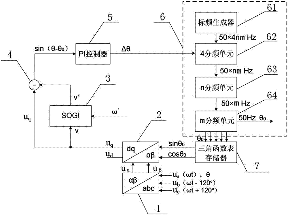
[0067] like figure 1 As shown, the three-phase digital phase-locked loop provided by the present invention includes a Clark transformation unit 1, a Park transformation unit 2, a second-order generalized integrator (Second Order Generalized Integra, SOGI) 3, a subtractor 4, a PI controller 5, a local Synchronization signal generation unit 6 and trigonometric function table memory 7.

[0068] Clark transformation unit 1 is connected to Park transformation unit 2, and Clark transformation unit 1 collects the three-phase grid voltage u a , u b , u c , voltage u a The corresponding phase is θ (θ=ωt), and the voltage u b The corresponding phase is (θ-120°), the voltage u c The corresponding phase is (θ+120°), and the three-phase grid voltage is equivalently synthesized into a rotation vector with value V and angular frequency ω. Clark transformation unit 1 converts the three-phase grid voltage u represented by t...

Embodiment 2

[0093] Embodiment 2, a three-phase digital phase-locking method.

[0094] refer to figure 1 , the three-phase digital phase-locking method provided by the present invention comprises the following steps:

[0095] a. Clark transformation unit 1 collects three-phase grid voltage u a , u b , u c And carry out Clark transformation to get the α-axis component u in the two-phase stationary coordinate system α and the β-axis component u β .

[0096] b, Park transformation unit 2 receives the local synchronization signal phase θ output by the trigonometric function table memory 7 0 The sine and cosine values ​​of , and the α-axis component u in the two-phase stationary coordinate system α and the β-axis component u β Perform Park transformation to obtain the q-axis component u in the two-phase rotating coordinate system q .

[0097] The trigonometric function table memory 7 outputs the sine and cosine values ​​of m groups of discrete, different-angle local synchronous signal...


PUM


Abstract

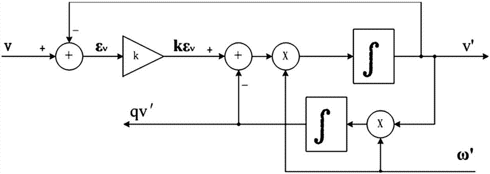
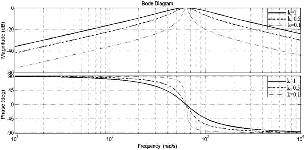
The invention provides a three-phase digital phase-locked loop and a phase-locked method. The three-phase digital phase-locked loop includes a Clark transformation unit, a Park transformation unit, a second-order generalized integrator, a subtractor, a PI controller, a local synchronous signal generation unit and a trigonometric function table memory. In the present invention, the output uq of the Park transformation unit is used as the input v of the second-order generalized integrator, and the center frequency of the second-order generalized integrator is set to 100 Hz, then the output v´ of the second-order generalized integrator is The second harmonic sin2ωt in the negative sequence component, and then using the subtractor to make the difference between uq and v´, can eliminate the interference of the second harmonic, so that the three-phase digital phase-locked loop can track the phase of the power grid normally. Moreover, the present invention uses a crystal oscillator to generate a standard frequency signal, and then forms a 50 Hz local synchronization signal through frequency division. Therefore, the phase-locked loop does not need to track the frequency of the grid, but only the phase.

Description

technical field [0001] The invention relates to a phase-locked loop, in particular to a three-phase digital phase-locked loop and a phase-locked method. Background technique [0002] In some power electronic equipment associated with the three-phase power grid, it is very important to obtain the real-time fundamental phase of the three-phase power grid. The automatic closed-loop control system that keeps synchronization with the frequency is widely used and can be used to track the grid phase in the control process of power electronic equipment. [0003] The three-phase voltage of the three-phase power grid will become unbalanced under instantaneous faults or under certain circumstances. This unbalanced three-phase voltage can be expressed as a collection of a series of unbalanced harmonic components. Generally, the three-phase voltage can be expressed as a collection of positive sequence components, negative sequence components and zero sequence components. For the distri...

Claims


Application Information

Patent Timeline
Patent Type & Authority Patents(China)
IPC IPC(8): H03L7/08
Inventor 陆原汪周玮郭素兵王少龙魏大鹏
Owner HEBEI UNIVERSITY
Learn More