Supercharge Your Innovation With Domain-Expert AI Agents!

Electric tool

A technology of electric tools and brushless motors, which is applied in the direction of manufacturing tools and portable mobile devices, and can solve problems such as mode shifting

Active Publication Date: 2014-11-19
PANASONIC INTELLECTUAL PROPERTY MANAGEMENT CO LTD
View PDF6 Cites 5 Cited by
  • Summary
  • Abstract
  • Description
  • Claims
  • Application Information

AI Technical Summary

Problems solved by technology

Specifically, as in Patent Document 1 Image 6 As shown, the appearance pattern of the rotational position signal is continuous under normal conditions, but sometimes deviates from the appearance pattern during abnormal conditions.

Method used


Image

  • Electric tool
  • Electric tool
  • Electric tool

Examples


Embodiment Construction

[0026] Next, an electric power tool according to one embodiment of the present invention will be described with reference to the drawings.

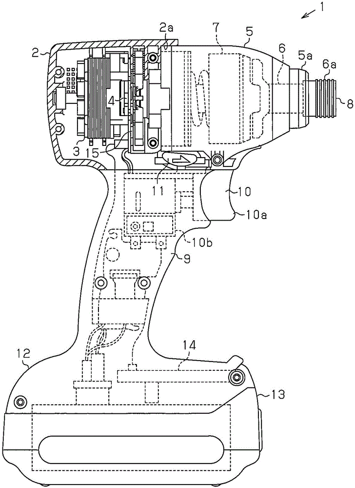
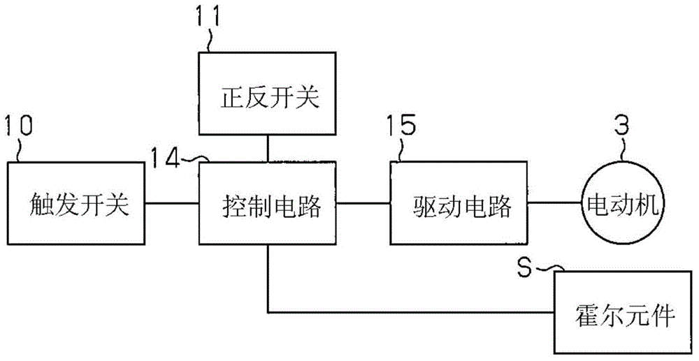
[0027] Such as figure 2 As shown, the electric tool 1 of the present embodiment includes: a motor 3 as a drive source; a Hall element S as a sensor unit that detects the rotational position of the motor 3 and outputs a position information signal for notifying a change in the rotational position; A circuit 15 that supplies power to the motor 3 ; and a control circuit 14 as a control unit that controls the drive circuit 15 .

[0028] exist figure 1 In the example shown, the motor 3 is accommodated in a cylindrical motor case 2 having an open end 2a and a bottom, and the rotation shaft 4 of the motor 3 is in the axial direction of the motor case 2 ( figure 1 left and right direction) to extend. Attached to the open end 2a of the motor case 2 is a dome 5 whose diameter gradually decreases from the base end toward the front end 5a. An ...


PUM


Abstract

The control circuit (14) of an electric tool (1) estimates the output interval of a sensor signal from a hole element (S) on the basis of the rotational speed of a motor (3), and sets an abnormality detection time in accordance with the estimated output interval. After actually detecting the sensor signal from the hole element (S), the control circuit (14) determines that there is an abnormality when a subsequent sensor signal is not verified within the abnormality detection time. The control circuit (14) is provided with an abnormality detection time algorithm in which the abnormality detection time is set shorter the faster the rotational speed of the motor (3), and the abnormality detection time is set longer the slower the rotational speed of the motor.

Description

technical field [0001] The present invention relates to an electric tool provided with a brushless motor. Background technique [0002] In recent years, an electric tool using a brushless motor as a drive source has been known. In the electric tool disclosed in Patent Document 1, the position of the rotor of the brushless motor is detected by a rotational position detection sensor, and the timing of energizing the armature winding of the brushless motor is set based on the position information. [0003] In addition, in the electric power tool of Patent Document 1, a protective operation for preventing failure of the motor due to an abnormality in a rotor position signal obtained by a rotational position detection sensor is implemented. Specifically, as in Patent Document 1 Figure 6 As shown, the appearance pattern of the rotational position signal is continuous under normal conditions, but sometimes deviates during abnormal conditions. When an abnormality is detected, a m...

Claims


Application Information

Patent Timeline
Patent Type & Authority Applications(China)
IPC IPC(8): B25F5/00
CPCB25F5/00
Inventor 宫崎博池田昌树
Owner PANASONIC INTELLECTUAL PROPERTY MANAGEMENT CO LTD
Features
  • R&D
  • Intellectual Property
  • Life Sciences
  • Materials
  • Tech Scout
  • Unparalleled Data Quality
  • Higher Quality Content
  • 60% Fewer Hallucinations
Learn More