
A circulating guide plate device for the ball forming mechanism of a bar rolling machine

A ball rolling and guide plate technology, which is used in guiding/positioning/aligning devices, mechanical equipment, bearing components, etc., can solve the problems of easy-to-scratch rolling pieces, inability to complete normal rolling, and inability to achieve continuous rolling, etc. The effect of continuous rolling

Inactive Publication Date: 2015-12-09
XI AN JIAOTONG UNIV
View PDF7 Cites 0 Cited by
  • Summary
  • Abstract
  • Description
  • Claims
  • Application Information

AI Technical Summary

Problems solved by technology

The first type is the ordinary long plate. In order not to interfere, the part in contact with the rolled piece is often relatively narrow, which is easy to scratch the rolled piece. When rolling small balls, due to the limitation of the gap between the rolls, the guide plate will always be in contact with the roll. Interference occurs, this method cannot complete normal rolling; the second method is improved on the basis of the first one, and many grooves are opened for the long plate according to the curved surface of the roll, and the position of the groove is at the convex edge of the roll. There will be interference, the length of the guide plate is fixed, and the machine must be stopped to change the position of the guide plate after rolling a bar, and continuous rolling cannot be realized

Method used


Image

  • A circulating guide plate device for the ball forming mechanism of a bar rolling machine
  • A circulating guide plate device for the ball forming mechanism of a bar rolling machine
  • A circulating guide plate device for the ball forming mechanism of a bar rolling machine

Examples


Embodiment Construction

[0014] The present invention will be further described in detail below in conjunction with the drawings.

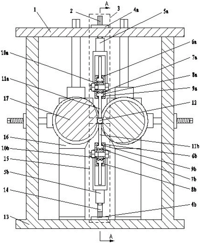
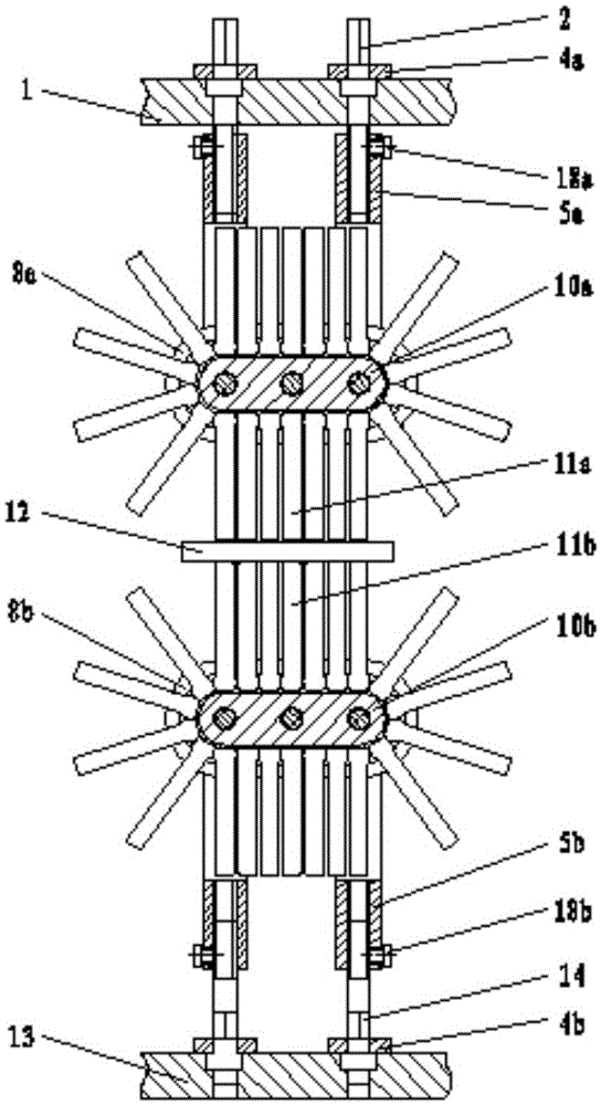
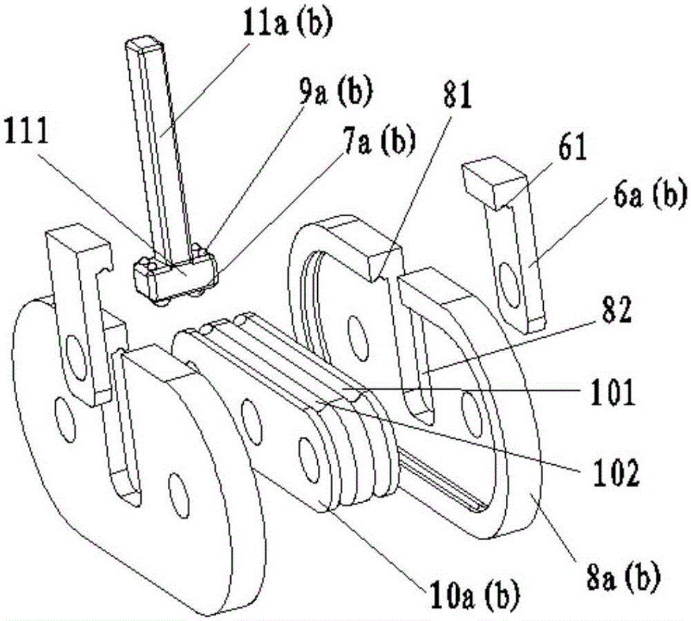
[0015] Reference figure 1 , figure 2 with image 3 , A circulating guide plate device for the ball forming mechanism of a bar rolling mill, comprising an upper frame 1, the upper frame 1 is connected to the lower frame 13, and the lower frame 13 is fixedly connected with 4 symmetrically arranged bearing seats 16, The bearing seat 16 is connected with two rollers 17 arranged symmetrically, and a bar 12 is placed between the two rollers 17, and the bar 12 is positioned in the vertical direction by the upper guide plate 3 and the lower guide plate 15;

[0016] The upper guide plate 3 includes two upper adjustment screws 2 symmetrically arranged in the axial direction of the roll. The upper adjustment screws 2 are rotatably connected with the upper frame 1 and are positioned by the first screw pressing plate 4a. The first screw pressing plate 4a is connected to the upper frame 1...


PUM


Abstract

A circular guide plate device of a ball forming mechanism of a bar ball rolling machine comprises an upper guide plate, a lower guide plate, and is mounted between two rollers of the ball rolling machine. The upper guide plate and the lower guide plate are respectively composed of an inner guide rail, an outer guide rail, an outer guide rail cut block, guide bars, a guide plate support and balls. The inner guide rails and the outer guide rails are connected with the outer guide rail cut blocks through bolts. The balls are mounted at the lower ends of the guide bars, and the balls on the lower portions of the guide bars are matched with the outer rail bodies of the inner guide rails. The balls on the upper portions of the guide bars are matched with inner rail bodies of the outer guide rails. The guide bars are distributed between the inner rail bodies and the outer rail bodies and make circular movement under driving of roller curve faces. The upper guide plate and the lower guide plate are connected with a machine frame through adjusting bolts, and the distance between the guide plates and a rolling piece can be adjusted by rotating the adjusting screw rods. According to the circular guide plate device of the ball forming mechanism of the bar ball rolling machine, the gap in the upper guide plate, the lower guide plate and the rolling piece can be adjusted quickly, the guide bars make circular movement along with the rollers, continuous rolling is achieved, and the working efficiency of the bar ball rolling machine is improved.

Description

Technical field [0001] The invention belongs to the technical field of bar rolling mills, and particularly relates to a circulating guide plate device of a ball forming mechanism of a bar rolling mill. Background technique [0002] The bar rolling mill, that is, the spiral groove cross rolling mill, generally consists of a pair of rolls, a pair of guide plates, two sets of bearing seats, and an axial adjustment device, a radial adjustment device, an inclination adjustment device and a frame. Its working principle is: two rolls with spiral grooves, their axis lines cross each other, the two rolls rotate in the same direction, the bar enters from the entrance end of the ball mill, and the bar rotates and advances under the action of the rolls. , It becomes a ball when it moves to the other end. [0003] The guide plate is one of the important tools in the skew rolling forming process. It forms a space for the deformation of the rolling piece together with the roll pass. The function...

Claims


Application Information

Patent Timeline
Patent Type & Authority Patents(China)
IPC IPC(8): B21B39/16B21H1/14
Inventor 赵升吨贾良肖李省张童童金立波吴士波
Owner XI AN JIAOTONG UNIV
Learn More