Steering control method for self-balancing two-wheeled vehicle

A technology for steering control and two-wheeled vehicles, which is applied to bicycles, motorcycles, motor vehicles, etc., and can solve the problems that the turning handle takes up a lot of space and has a complicated structure

Inactive Publication Date: 2014-11-26
重庆鹏得基业汽车部件有限公司
View PDF5 Cites 39 Cited by
  • Summary
  • Abstract
  • Description
  • Claims
  • Application Information

AI Technical Summary

Problems solved by technology

[0002] Now there are self-balancing two-wheeled vehicles on the market, and they are more and more popular among young people. They are also called camera vehicles abroad. The advantages of this kind of vehicle are small size, convenient travel, and built-in high-precision gyroscope. According to the angle of inclination, the speed of the motor can be maintained and controlled to achieve the purpose of self-balancing. Now the popular self-balancing two-wheeled vehicles are equipped with rotating handles to control the steering function of the car. There are steering shafts and other parts inside. The disadvantage is that turning the handle takes up a lot of space, and you need to use both hands to control the direction
[0003] There is also a self-balancing two-wheeled vehicle on the market that does not need a handle to control the steering, such as the CN 103600795 A Chinese invention patent disclosed on February 26, 2014, which discloses a self-balancing two-wheeled vehicle based on a disc grating , the original rotating handle is canceled in this two-wheeled vehicle, and the original hand rotation is replaced by a foot rotation, which liberates the driver's hands and improves driving pleasure, but this patent still has the disadvantage of a relatively complicated structure. Compared with the traditional handle to rotate the two-wheeled vehicle, the patent newly installed a disc grating sensor

Method used


Image

  • Steering control method for self-balancing two-wheeled vehicle
  • Steering control method for self-balancing two-wheeled vehicle
  • Steering control method for self-balancing two-wheeled vehicle

Examples


Embodiment Construction

[0021] The specific embodiment of the present invention will be further described below in conjunction with accompanying drawing:

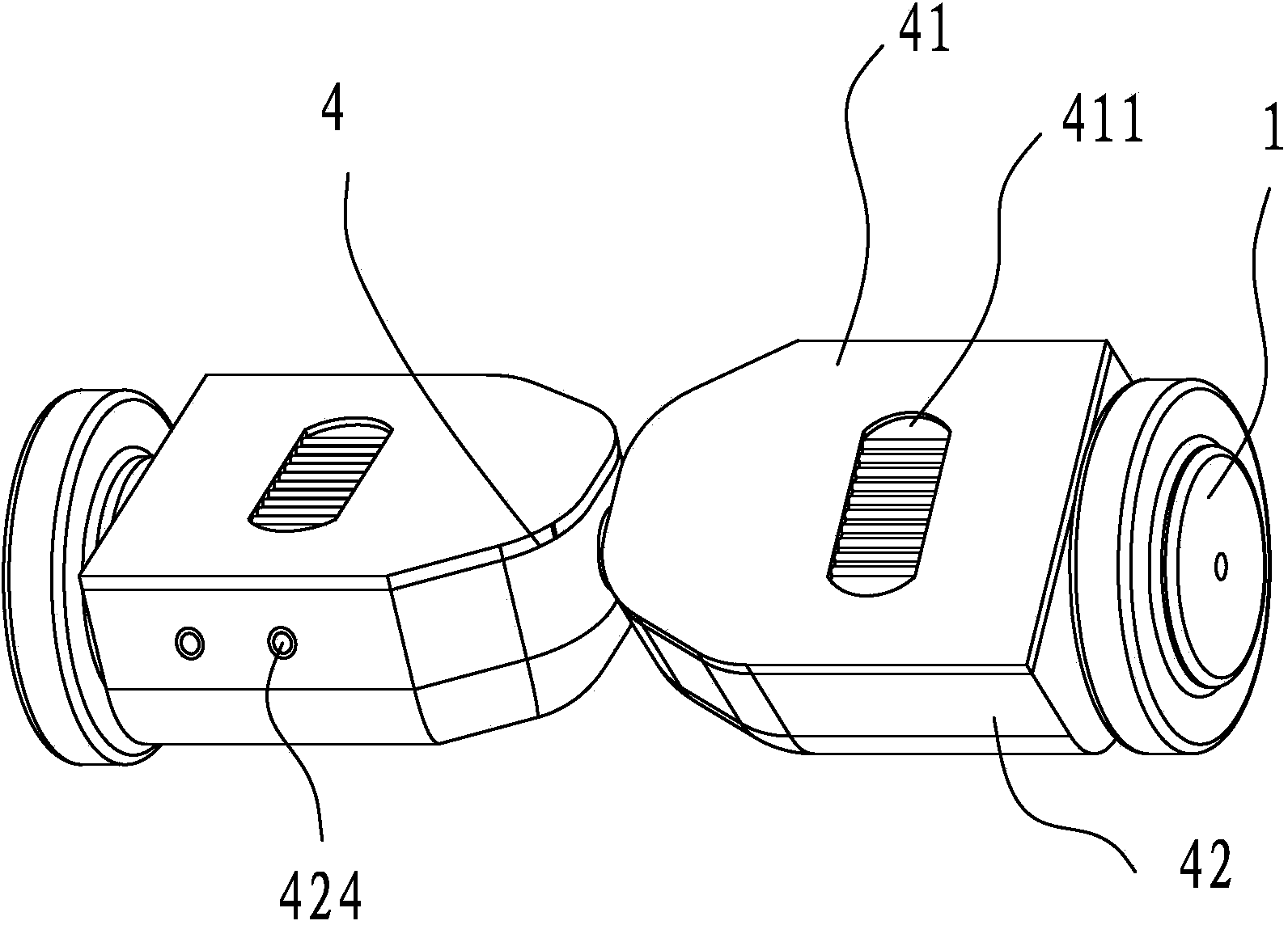
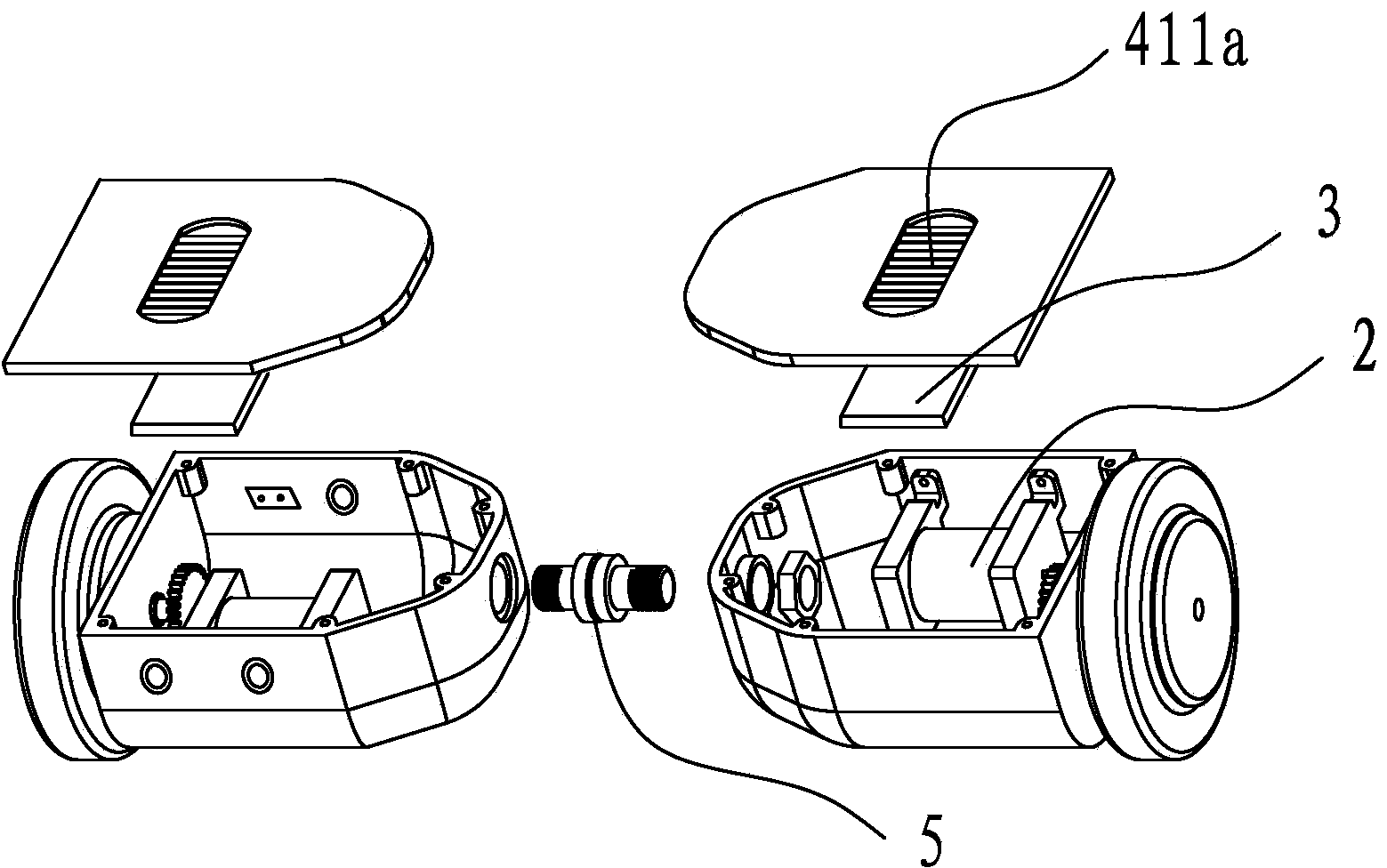
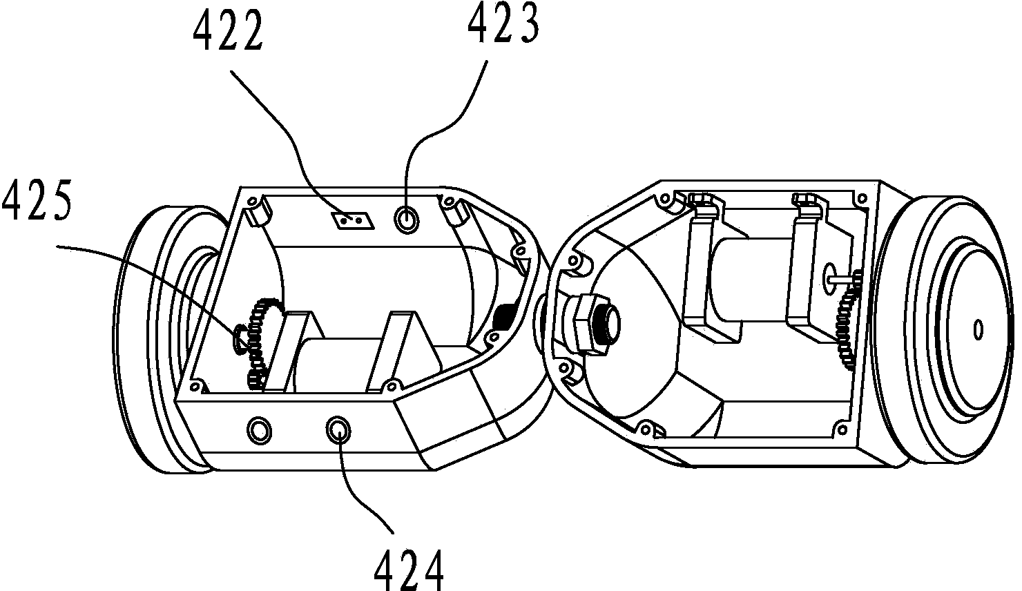
[0022] Such as Figure 1 to Figure 4 As shown, a steering control method for a self-balancing two-wheeled vehicle includes a main frame of the vehicle body, wheels 1 are arranged on both sides of the main frame of the vehicle body, a motor 2 and a gyroscope 3 capable of controlling the speed of the motor are arranged in the main frame of the vehicle body , the main frame of the car body includes two split frames 4 that are separated from each other, a connecting shaft 5 is arranged in the middle of the two split frames, and the two split frames rotate independently with the connecting shaft as the rotation center. A gyroscope and a motor are separately provided in a split frame. The split frame includes an upper cover pedal 41 and a lower housing 42. The inner wall of the lower housing is provided with 6 threaded columns, and the upper cover pedal...


PUM


Abstract

The invention discloses a steering control method for a self-balancing two-wheeled vehicle. The two-wheeled vehicle comprises two separated split frames, a connecting shaft is arranged between the two split frames, and motors and gyroscopes capable of controlling the rotating speed of the motors are arranged in the split frames. The steering control method for the self-balancing two-wheeled vehicle comprises the following steps that firstly, the outer split frame needing to turn is treaded by the foot, and the inner split frame is kept horizontal. According to the split frame in the horizontal state, due to the fact that the gyroscope does not induct changes of the inclination angle, the motor does not rotate, the gyroscope at the bottom of an upper cover pedal inducts the changes of the inclination angle after inclination, signals are output to a circuit board to enable the motor to rotate, and therefore wheels are driven to rotate. Finally, one wheel does not rotate, the other wheel rotates, the two-wheeled vehicle turns and moves with the wheel which does not rotate as the center, the acceleration, speed reduction and turning functions can be achieved through foot treading, and the structure is simple.

Description

technical field [0001] The invention relates to a steering control method of a self-balancing two-wheeled vehicle. Background technique [0002] Now there are self-balancing two-wheeled vehicles on the market, and they are more and more popular among young people. They are also called camera vehicles abroad. The advantages of this kind of vehicle are small size, convenient travel, and built-in high-precision gyroscope. According to the angle of inclination, the speed of the motor can be maintained and controlled to achieve the purpose of self-balancing. Now the popular self-balancing two-wheeled vehicles are equipped with rotating handles to control the steering function of the car. There are steering shafts and other parts inside. The disadvantage is that turning the handle takes up a lot of space, and you need to use both hands to control the direction. [0003] There is also a self-balancing two-wheeled vehicle on the market that does not need a handle to control the ste...

Claims


Application Information

Patent Timeline
Patent Type & Authority Applications(China)
IPC IPC(8): B62K11/00B62M6/45
CPCB62K11/007
Inventor 祝珍海
Owner 重庆鹏得基业汽车部件有限公司
Why Eureka
Try Eureka