Turning jig device and manufacturing method dedicated to crankshaft

A fixture and crankshaft technology, applied in positioning devices, turning equipment, clamping devices, etc., can solve the problems of high technical level requirements, powerlessness, and investment of processors

Active Publication Date: 2015-12-02
沈阳机床中捷友谊厂有限公司
View PDF11 Cites 0 Cited by
  • Summary
  • Abstract
  • Description
  • Claims
  • Application Information

AI Technical Summary

Problems solved by technology

[0003] Today's three processing methods have their own advantages and disadvantages. The first method can mill the crankshaft's connecting rod neck, main journal and web. The technical level requirements are very high and other factors are limited. In addition, many large-scale turning-milling machine tools need to be imported from abroad.
The second case is the commonly used processing method now. Different eccentric fixtures are designed according to the different eccentricity of each crankshaft connecting rod journal and the phase indexing angle of the connecting rod journal to process the crankshaft. The disadvantage is that each fixture can only To process the connecting rod neck and web of a specific crankshaft, different fixtures need to be designed for different series of crankshafts, resulting in a waste of money and inconvenient replacement of fixtures
This feature makes these journals completely impossible to machine on conventional lathes
There is a main shaft diameter between the two connecting rod journals, and these main shaft diameters are at the same center, so after the chuck of the traditional lathe clamps the main shaft diameters at both ends, other main shaft diameters of the crankshaft can be processed, but for connecting rods that are not at the same rotation center Neck processing is helpless, if you want to process, you must take special measures
[0006] 2. The traditional method of processing each type of crankshaft needs to design a set of special tooling according to the characteristics of the workpiece to process the crankshaft
As a result, if there are many types of crankshafts to be processed, tooling must be designed separately according to the characteristics of the crankshafts, resulting in huge capital investment and affecting processing efficiency.
At the same time, this kind of fixture is generally limited to processing the connecting rod neck. When the spindle diameter needs to be processed, the tooling needs to be removed from the lathe spindle, and the spindle diameter is processed after replacing the ordinary chuck, which greatly affects the processing efficiency.

Method used


Image

  • Turning jig device and manufacturing method dedicated to crankshaft
  • Turning jig device and manufacturing method dedicated to crankshaft
  • Turning jig device and manufacturing method dedicated to crankshaft

Examples


Embodiment Construction

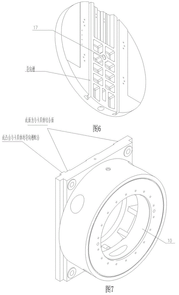
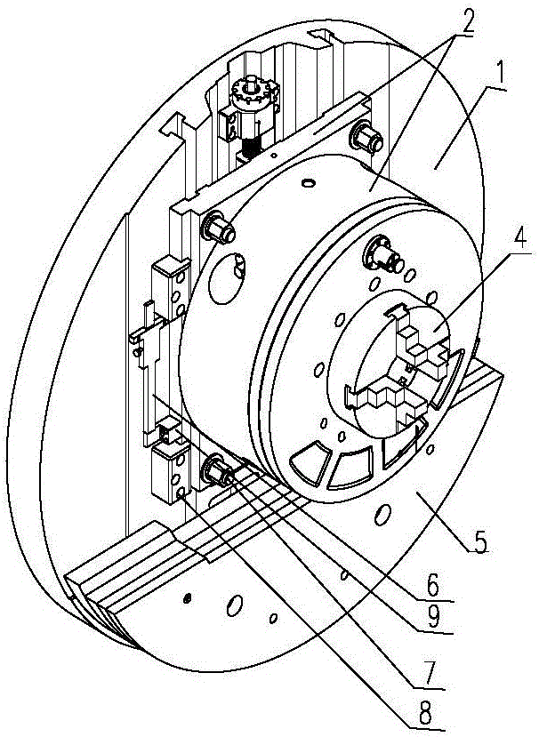
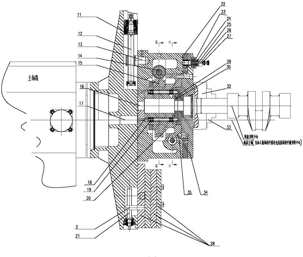
[0029] The special turning fixture device for crankshaft, including left and right fixtures, is characterized in that the left and right fixtures are symmetrically installed on the left and right rotation centers of the lathe, and the structures of the left and right fixtures are basically the same, and each fixture is moved by the concrete and eccentric distance. And positioning mechanism, connecting rod neck index positioning and locking mechanism, crankshaft clamping mechanism, eccentric weight mechanism; the structure of each part is shown in the attached drawings as follows:

[0030] The main structure of the fixture see figure 1, the card specific 1 is used as the load-bearing body, which is characterized in that the left and right fixtures are symmetrically installed on the left and right rotation centers of the machine tool through the card specific 1, and one end can be the headstock, the other end can be the tailstock, or both the left and right are the headstock . ...


PUM


Abstract

The invention discloses a turning clamp device special for a bent axle and a manufacturing method. A left clamp and a right clamp are basically identical in structure. The turning clamp device special for the bent axle is characterized in that an eccentric distance moving and positioning mechanism of each clamp is installed on a clamp body through a lead screw supporting mechanism, and pressing plates, a position-measuring mechanism and a screw-locking mechanism carry out locking and positioning on a sliding plate; a connecting rod neck indexing positioning and locking mechanism is installed in a conical frustum of the sliding plate, a worm gear is fixed to a drum wheel, a rotary disc is fixed to the drum wheel through a positioning pin, a worm drives the worm gear to rotate around a rotation central hole, and therefore rotation, positioning and fixing locking of a workpiece are achieved; a bent axle clamping mechanism can rotate around the rotation central hole in an indexing mode while clamping the workpiece; an eccentric balance weight mechanism achieves rotary balance of a whole rotary system. By means of the eccentric clamp on a main shaft of a lathe, bent axles of multiple series, different eccentric distances and different main shaft neck diameters can be machined on one device, only one time of clamping is needed in the machining process of each bent axle, and then a connecting rod neck, the main shaft neck and web plates at two sides of the bent axle are turned.

Description

technical field [0001] The invention relates to mechanical equipment manufacturing, and relates to an eccentric fixture installed on the main shaft of a machine tool, and is a turning fixture device suitable for processing connecting rod journals, main journals and web plates on both sides of crankshafts of various specifications. Background technique [0002] Main journal, connecting rod journal and web of the crankshaft are mainly processed in the following three ways at this stage: the first is to use the five-axis turning and milling center for multi-axis simultaneous milling, and the second is to process according to the characteristics of each series of crankshafts Manufactured eccentric jig for processing, the third is the most traditional way, according to the difference in eccentricity of the crankshaft connecting rod neck, punch a special eccentric hole on the end face of the crankshaft to process the connecting rod neck. [0003] Today's three processing methods h...

Claims


Application Information

Patent Timeline
Patent Type & Authority Patents(China)
IPC IPC(8): B23Q3/12B23B5/22
CPCB23Q3/12B23Q16/06B23Q2703/105
Inventor 贺鑫元张铮常博宇吕建华尹猛曹小强富伟姜海洋陈丽杰安云祥
Owner 沈阳机床中捷友谊厂有限公司
Why Eureka
Try Eureka