Aluminum cutting machine

A cutting machine, aluminum technology, applied in the direction of shearing device, accessories of shearing machine, shearing machine equipment, etc., can solve the problems of troublesome adjustment, affecting accuracy, and indirect way of adjusting angle, etc., to achieve direct operation, improve Product qualification rate, the effect of ensuring accuracy

Active Publication Date: 2016-06-01
黄广生
View PDF7 Cites 4 Cited by
  • Summary
  • Abstract
  • Description
  • Claims
  • Application Information

AI Technical Summary

Problems solved by technology

[0005] ①The way to adjust the angle is not direct, it needs to be converted, and the operation is troublesome
The adjustment principle of the above-mentioned angle adjustment device is as follows: the lengths of the two sides of a triangle are fixed, and the degree of the angle between the two fixed sides is changed by changing the length of the third side, but in this case, the length of the triangle The shape will inevitably change, that is, the vertical angle of the adjusting bolt will inevitably change, then at least two conversions are required to calculate the included angle between the two fixed sides, and the adjustment will be more troublesome; if the included angle is measured manually while adjusting Angles are also cumbersome and prone to deviation
[0006] ②Small adjustment range
Because the shape of the triangle changes after the adjusting bolt is rotated, and the adjusting bolt passes through the sliding base and is fixed on the sliding base by a nut, so the angle of the adjusting bolt's deflection to the left and right in the direction of the original state is limited, so that the cutting disc Angular range of adjustment is small
[0007] ③It is easy to loosen during the working process, which affects the accuracy
Since the adjusting bolt and the sliding base are fixed by nuts, the adjusting bolt is easily loosened due to the impact of work during the aluminum material cutting process, thereby changing the angle of the cutting cutter head, causing errors in the aluminum workpiece, and causing the high failure rate

Method used


Image

  • Aluminum cutting machine
  • Aluminum cutting machine

Examples


Embodiment Construction

[0019] The present invention is described in further detail by the following examples.

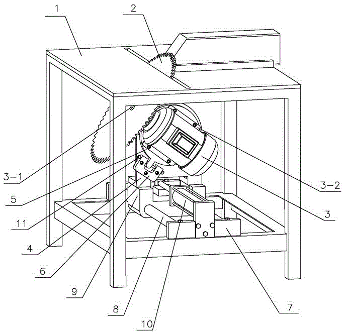
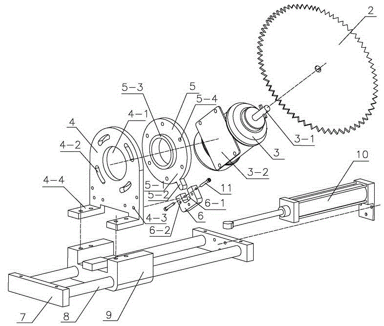
[0020] see Figure 1-Figure 2 As shown, an aluminum material cutting machine includes a cutting disc 2 arranged in a frame 1, a motor 3, a sliding base and an aluminum material transmission device arranged on the upper surface of the frame 1, and the motor output shaft 3-1 A cutting disc 2 is fixedly installed, and a part of the cutting disc 2 protrudes from the upper surface of the frame 1. The sliding base is composed of a guide rod support plate 7, a guide rod 8 and a sliding seat 9, and two guide rods 8 at both ends The upper part is supported and fixed by two guide rod support plates 7 fixed in the frame 1, the sliding seat 9 is slidingly connected with the guide rod 8, and an angle adjustment and positioning device is also provided between the motor fixing plate 3-2 and the sliding base. The angle adjustment positioning device is composed of a swing angle support seat 4, a Q-shaped ...


PUM


Abstract

The invention discloses an aluminum cutting machine. A cutting disc is mounted on a motor, an angle adjustment positioning device composed of a swing angle supporting seat, a Q-shaped rotary plate flange and a U-shaped fine adjustment block is arranged between the motor and a sliding base, both the Q-shaped rotary plate flange and the U-shaped fine adjustment block are fixedly mounted on the same side face of the swing angle supporting seat, the motor is fixedly connected with the other side face of the Q-shaped rotary plate flange, an external flange of the inner ring periphery of the Q-shaped rotary plate flange is embedded in a round through hole of the swing angle in a matched and adhered manner, a rotating rod of the Q-shaped rotary plate flange extends into the U-shaped opening of the U-shaped fine adjustment block, an adjusting gap is formed between the rotating rod and the U-shaped opening, adjusting bolts are mounted on the two side walls of the U-shaped opening respectively vertically, and the tail end of each adjusting bolt is in contact connection with the rotating rod of the Q-shaped rotary plate flange. By the aluminum cutting machine, the angle adjustment mode of the cutting disc is visual, accurate and convenient, the angle adjustment range is wide, and all the parts of the angle adjustment positioning device cannot loosen during working.

Description

technical field [0001] The invention relates to an aluminum material processing equipment, in particular to an aluminum material cutting machine. Background technique [0002] In the field of aluminum processing, aluminum cutting machines are widely used processing equipment. Because it is necessary to adjust various angles when cutting aluminum, or because the aluminum will have deviations during the early processing, it is necessary to accurately adjust the angle of the cutting disc of the aluminum cutting machine frequently to ensure the cutting quality. The aluminum conforms to the required shape or compensates for deviations caused by previous processing. [0003] The cutting blade angle adjustment device of the existing aluminum material cutting machine is an adjusting bolt, which is hinged with the motor placement plate supporting the motor and the cutting blade, and the motor placement plate is hinged with the sliding base, and the adjusting bolt passes through the ...

Claims


Application Information

Patent Timeline
Patent Type & Authority Patents(China)
IPC IPC(8): B23D19/00B23D33/02
Inventor 黄广生
Owner 黄广生
Why Eureka
Try Eureka