Check patentability & draft patents in minutes with Patsnap Eureka AI!

Cover for constant velocity coupling

A coupling and constant velocity technology, applied in the direction of couplings, elastic couplings, mechanical equipment, etc., can solve the problems of belt breakage, increased reaction force of thick-walled parts, and large compressive deformation of thick-walled parts, etc. Achieving the effect of large shrinkage rate and suppressing the deterioration of sealing performance

Active Publication Date: 2016-09-28
HONDA MOTOR CO LTD
View PDF10 Cites 0 Cited by
  • Summary
  • Abstract
  • Description
  • Claims
  • Application Information

AI Technical Summary

Problems solved by technology

However, in this case, the amount of compressive deformation of the thick portion increases, and as a result, the reaction force of the thick portion increases.
Therefore, excessive tension is generated in the belt, and there is also a possibility that the belt breaks

Method used


Image

  • Cover for constant velocity coupling
  • Cover for constant velocity coupling
  • Cover for constant velocity coupling

Examples


Embodiment Construction

[0031] Hereinafter, preferred embodiments of the cover for a constant velocity coupling (hereinafter simply referred to as a cover) according to the present invention will be described in detail with reference to the drawings.

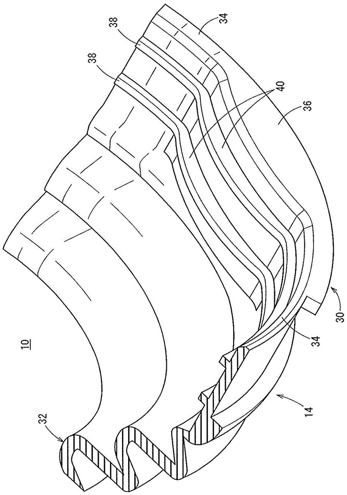
[0032] figure 1 It is an exploded perspective view of a tripod-type constant velocity coupling 12 to which the cover 10 according to the present embodiment is attached. In addition, in figure 1 In FIG. 2 , internal members constituting the constant velocity coupling 12 are omitted for illustration.

[0033] First, the constant velocity coupling 12 will be described. The constant velocity coupling 12 has an outer member 16 and an inner member (both not shown) inserted into a bottomed hole formed in the outer member 16 .

[0034] The outer member 16 has a long shaft portion 18 and a cup-shaped portion 20 provided at the front end portion of the shaft portion 18 . A differential gear (not shown) is connected to the shaft portion 18 , and the rotationa...


PUM


Abstract

The invention relates to a cover used for a constant-velocity coupling. The cover (10) used for the constant-velocity coupling is provided with a large-diameter annular part (30) externally embedded in a cup-shaped part (20). The outer wall of the cup-shaped part (20) is provided with arc surfaces (24a-24c) and concave parts (26a-26c), so that the outline of the cup-shaped part (20) is in a non-cylinder shape. The large-diameter annular part (30) is provided with a thin-wall part (34) and a thick-wall part (36) set to be thicker than the thin-wall part (34). A first sealing part (38) is convexly formed on the inner wall of the arc-shaped thin-wall part (34) arranged along the arc surfaces (24a-24c) of the cup-shaped part (20). In addition, a second sealing part (40), which is larger than the first sealing part (38) in protruding length, is convexly formed on the inner wall of the convex thick-wall part (36) arranged along the concave parts (26a-26c) of the cup-shaped part (20).

Description

technical field [0001] The present invention relates to a cover for a constant velocity coupling that is attached to a cup-shaped portion that constitutes an outer member of a constant velocity coupling and has a non-cylindrical outer shape. Background technique [0002] Constant velocity couplings used in automobiles etc. are mainly composed of outer parts and inner parts. The outer member has a bottomed cylindrical cup and a shaft protruding from the bottom of the cup. The inner member is fixed to the front end portion of the driving force transmission shaft, and is inserted into the cup-shaped portion of the outer member. In addition, a part of the driving force transmission shaft is covered with a cover for a constant velocity coupling (hereinafter referred to simply as a cover) from the tip of the cup-shaped portion. Specifically, the cover is formed of an elastomeric material such as thermoplastic resin, and has a large-diameter annular portion fitted on the cup-shap...

Claims


Application Information

Patent Timeline
Patent Type & Authority Patents(China)
IPC IPC(8): F16D3/84
Inventor 坊野康晴
Owner HONDA MOTOR CO LTD
Features
  • R&D
  • Intellectual Property
  • Life Sciences
  • Materials
  • Tech Scout
  • Unparalleled Data Quality
  • Higher Quality Content
  • 60% Fewer Hallucinations
Learn More