Check patentability & draft patents in minutes with Patsnap Eureka AI!

Steam turbine facility

a technology of steam turbines and facilities, applied in the direction of liquid degasification, valve housings, separation processes, etc., can solve the problems of deterioration and concern of sealability of gaskets, and achieve the effects of suppressing the decline of sealability, high sealability, and preventing deformation

Active Publication Date: 2014-09-30
MITSUBISHI POWER LTD
View PDF15 Cites 0 Cited by
  • Summary
  • Abstract
  • Description
  • Claims
  • Application Information

AI Technical Summary

Benefits of technology

The solution effectively maintains high sealability and prevents deformation of components, ensuring reliable sealing even at extreme temperatures, thereby improving the reliability and service life of the steam turbine facility.

Problems solved by technology

In this type of steam turbine facility used under harsh steam-temperature conditions, when the graphite type spiral-wound gasket described in Patent Literature 1 is used, there is a concern about deterioration of sealability of the gasket due to loss of graphite by oxidation.

Method used


Image

  • Steam turbine facility
  • Steam turbine facility
  • Steam turbine facility

Examples


Embodiment Construction

[0041]Embodiments of the present invention will now be described in detail with reference to the accompanying drawings. It is intended, however, that unless particularly specified, dimensions, materials, shape, relative positions and the like of components described in these embodiments shall be interpreted as illustrative only and not limitative of the scope of the present invention.

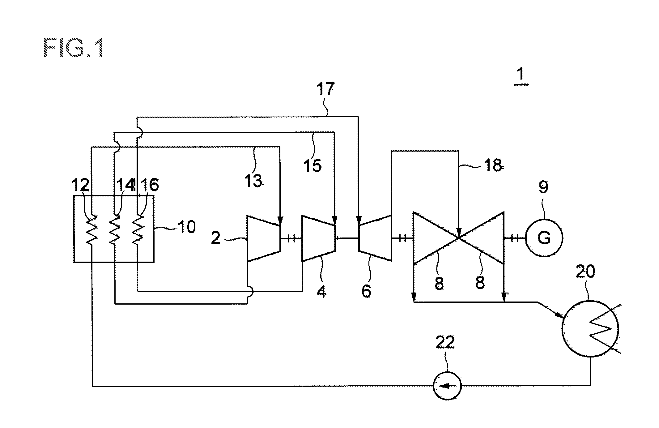
[0042]FIG. 1 is an illustration of an overall structure of a steam turbine facility according to one embodiment.

[0043]In one embodiment, a steam turbine facility 1 is provided with a turbine group formed by a very high pressure turbine 2, a high pressure turbine 4, an intermediate pressure turbine 6 and a low pressure turbine 8, a generator 9 driven by the turbine group, and a boiler 10 for producing steam to be supplied to the turbine group.

[0044]Further, shafts of the very high pressure turbine 2, the high pressure turbine 4, the intermediate pressure turbine 6 and the low pressure turbine 8 may be co...


PUM

PropertyMeasurementUnit
temperatureaaaaaaaaaa

Abstract

A steam turbine facility is provided which is capable of appropriately sealing a gap between members made of cast material of Ni-based alloy even under the steam-temperature condition of 650° C. or higher, and which includes a first member and a second member whose base material is formed of cast material composed of at least one of Ni-based alloy, austenite steel, or high-chrome steel, form a space where the steam of 650° C. or higher flows. Between the first member and the second member, a metal gasket is provided which has a plurality of portions in line contact with the first member and the second member. On the first member and the second member, a first high-hardness layer which is harder than the base material, is provided at least in a portion where each of the first member and the second member is in line contact with the metal gasket.

Description

TECHNICAL FIELD[0001]The present invention relates to a steam turbine facility in which steam whose temperature is 650° C. or higher is used.BACKGROUND ART[0002]In a steam turbine facility, steam is led from a boiler to a turbine casing via a pipe so as to drive the turbine by the steam. Further, a steam valve (a stop valve, a governing valve, etc) is provided in a steam pipe for supplying the steam to the turbine casing. The steam valve is configured to cut off the steam entering the turbine casing and to adjust the steam flow.[0003]In a conventional steam turbine facility, a graphite type spiral-wound gasket was mainly used for a seal portion of a flange connection part of the pipes, the steam valve, and the like. The graphite type spiral-wound gasket, herein, indicates a semi-metallic gasket formed by alternately winding a metallic hoop and a filler of graphite-type material into a spiral shape.[0004]For instance, described in Patent Literature 1 is a spiral gasket in which an ex...

Claims


Application Information

Patent Timeline
Patent Type & Authority Patents(United States)
IPC IPC(8): F01K13/02F01K21/06F01D11/00F01K21/00
CPCF01K21/00F01D11/00F01K7/18F01D11/005F01D25/00F01D25/24F05D2240/55F16J15/08F16K27/00Y02E10/72
Inventor NISHIMOTO, SHINHAMADA, KATSUHISATANAKA, YOSHINORISHINOHARA, TANEHIROAKAMATSU, TETSURO
Owner MITSUBISHI POWER LTD
Features
  • R&D
  • Intellectual Property
  • Life Sciences
  • Materials
  • Tech Scout
  • Unparalleled Data Quality
  • Higher Quality Content
  • 60% Fewer Hallucinations
Learn More