
Earthquake detection system and detection method

A detection system and earthquake technology, applied in seismology, geophysical measurement, measuring devices, etc., can solve the problems of high measurement accuracy, complex structure, and inability to detect earthquakes in a timely and accurate manner

Inactive Publication Date: 2014-12-03
BEIJING JIAYUE TONGLEJI ELECTRONICS
View PDF7 Cites 6 Cited by
  • Summary
  • Abstract
  • Description
  • Claims
  • Application Information

AI Technical Summary

Problems solved by technology

[0002] With the further development of seismology and earthquake prediction research and rapid response after major earthquakes, higher and higher requirements are put forward for earthquake detection work. However, the current earthquake detection equipment is not only complex in structure, but also has a single detection method and poor accuracy. , it is impossible to timely and accurately detect the occurrence of earthquakes. For example, Chinese patent document CN201110390546 discloses an earthquake detection method and system. The earthquake detection method and system can only perform earthquake detection from two aspects of tensor measurement and strain measurement. Very complex physical and chemical processes. During the earthquake process, the tensor and strain are very small, so the requirements for measurement accuracy are high, which makes the earthquake detection system unable to meet the existing needs in terms of accuracy.

Method used


Image

  • Earthquake detection system and detection method
  • Earthquake detection system and detection method
  • Earthquake detection system and detection method

Examples


Embodiment Construction

[0050] In order to describe the technical content, structural features, achieved goals and effects of the present invention in detail, the following will be described in detail in conjunction with the embodiments and accompanying drawings.

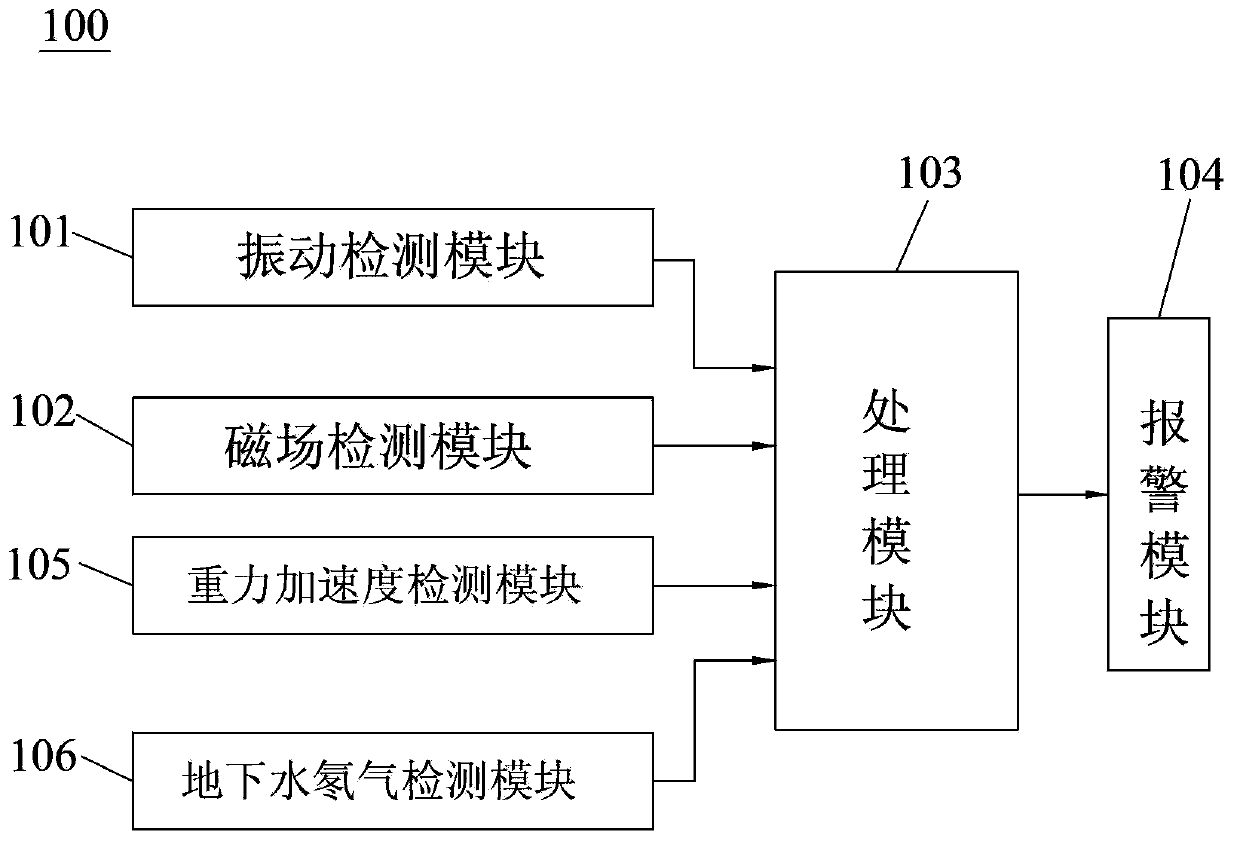
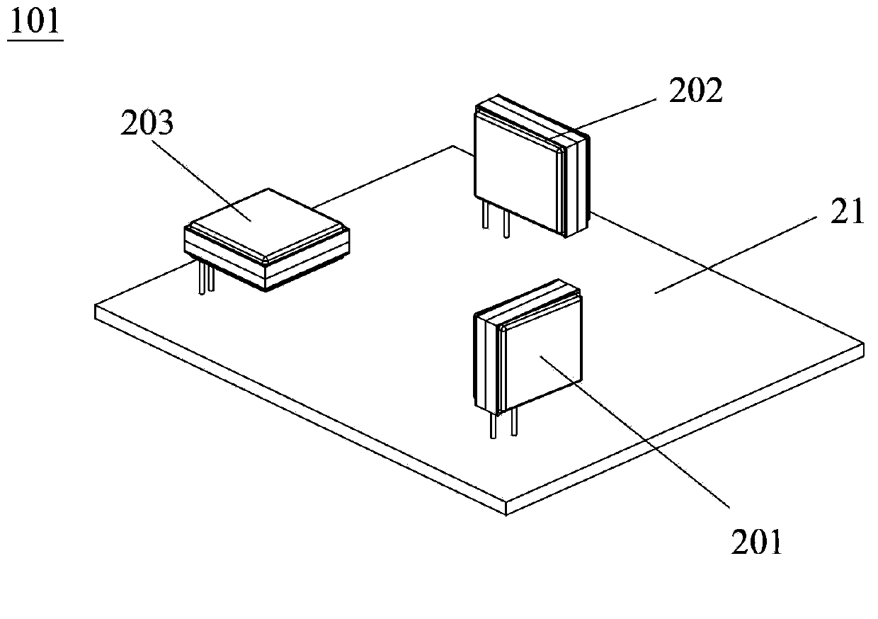
[0051] refer to figure 1 , the present invention discloses an earthquake detection system 100, the earthquake detection system 100 includes a vibration detection module 101, a magnetic field detection module 102, a processing module 103 and an alarm module 104, the vibration detection module 101 includes an X-axis vibration detection unit 201, The Y-axis vibration detection unit 202 and the Z-axis vibration detection unit 203 respectively detect vibration signals in the X-axis direction, the Y-axis direction and the Z-axis direction; the magnetic field detection module 102 includes an X-axis magnetic field detection unit 301 and a Y-axis magnetic field detection unit 302 and the Z-axis magnetic field detection unit 303 respectively detect ...


PUM


Abstract

The invention discloses an earthquake detection system consisting of a vibration detection module, a magnetic field detection module, a processing module and an alarm module. The vibration detection module includes an X shaft vibration detection unit, a Y shaft vibration detection unit, and a Z shaft vibration detection unit, wherein the three units are used for respectively detecting vibration signals at an X shaft direction, a Y shaft direction, and a Z shaft direction; the magnetic field detection module is composed of an X shaft magnetic field detection unit, a Y shaft magnetic field detection unit, and a Z shaft magnetic field detection unit, wherein the three units are used respectively for detecting magnetic variation signals at the X shaft direction, the Y shaft direction, and the Z shaft direction; the processing module caries out processing on the vibration signals and the magnetic variation signals and generates an alarm signal based on the vibration signals and the magnetic variation signals; and the alarm module carries out alarming according to the alarm signal. Compared with the prior art, the provided detection system has the following beneficial effects: earthquake detection can be carried out dynamically in real time in terms of terrestrial magnetism variation and vibration variation; detection can be carried out easily; and the detection precision is high. In addition, the invention also discloses an earthquake detection method.

Description

technical field [0001] The invention belongs to the technical field of micro-nano electronics, and in particular relates to an earthquake detection system and a detection method. Background technique [0002] With the further development of seismology and earthquake prediction research and rapid response after major earthquakes, higher and higher requirements are put forward for earthquake detection work. However, the current earthquake detection equipment is not only complex in structure, but also has a single detection method and poor accuracy. , it is impossible to timely and accurately detect the occurrence of earthquakes. For example, Chinese patent document CN201110390546 discloses an earthquake detection method and system. The earthquake detection method and system can only perform earthquake detection from two aspects of tensor measurement and strain measurement. The physical and chemical process is very complicated. During the earthquake process, the tensor and stra...

Claims


Application Information

Patent Timeline
IPC IPC(8): G01V1/00
Inventor 刘乐杰彭春雷
Owner BEIJING JIAYUE TONGLEJI ELECTRONICS
Learn More