
Humidity control method and system of fingerprint recognition equipment

A humidity control system, fingerprint recognition technology, applied in humidity control, control/regulation system, non-electric variable control, etc., can solve the problem of low humidity in the use environment, and achieve the effect of solving the problem of low or high humidity

Inactive Publication Date: 2014-12-03
FUJIAN STAR NET EVIDEO INFORMATION SYST CO LTD
View PDF6 Cites 15 Cited by
  • Summary
  • Abstract
  • Description
  • Claims
  • Application Information

AI Technical Summary

Problems solved by technology

[0005] One of the technical problems to be solved by the present invention is to provide a humidity control method for fingerprint identification equipment, which can protect the humidity of the fingerprint identification equipment itself from being too low or too high, and can also protect the humidity caused by human fingers. Protect against fingerprint recognition failure, and fundamentally solve the problem of low or high humidity in the environment where fingerprint recognition equipment is used

Method used


Image

  • Humidity control method and system of fingerprint recognition equipment
  • Humidity control method and system of fingerprint recognition equipment
  • Humidity control method and system of fingerprint recognition equipment

Examples


Embodiment 1

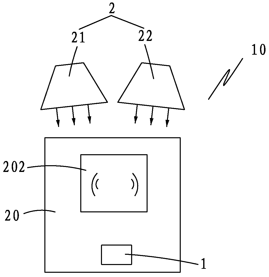
[0034] like figure 2As shown, the humidity control system 10 of the fingerprint identification device in this embodiment includes an air humidity detection device 1 and an air humidity control device 2 . The air humidity detection device 1 is arranged on the periphery of the sensing area 202 of the fingerprint identification device 20 to detect the air humidity in the sensing area 202 of the fingerprint identification device 20; the air humidity control device 1 is arranged on the top of the fingerprint identification device 20 Or the periphery of the sensing area 202 of the fingerprint identification device 20 to adjust the air humidity in the sensing area 202 of the fingerprint identification device 20; when the detected air humidity is lower than or higher than the preset air humidity threshold, an air The humidity control device 2 adjusts the air humidity in the sensing area 202 of the fingerprint identification device 20 until the air humidity in the sensing area 202 of ...

Embodiment 2

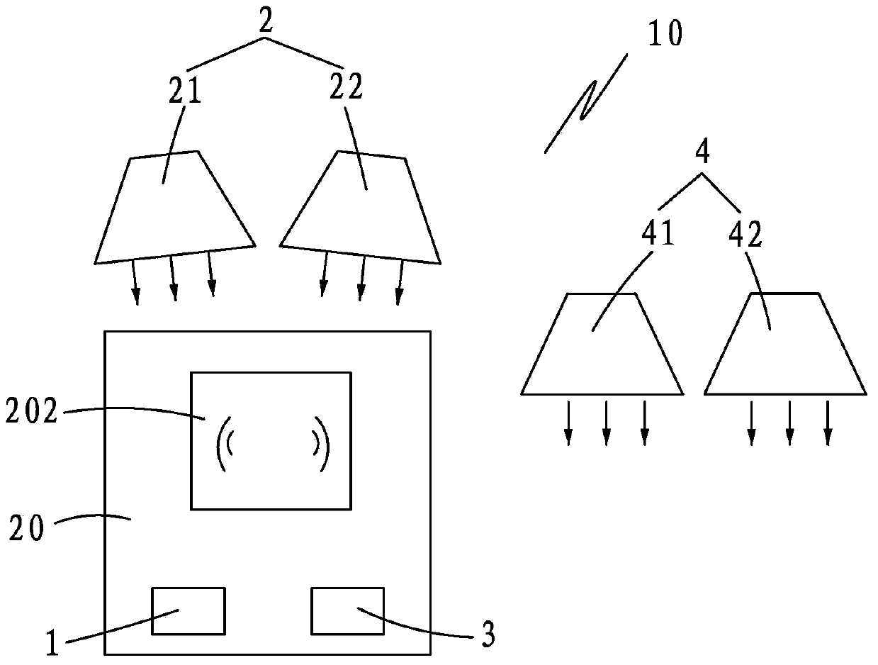
[0037] like image 3 As shown, the humidity control system of the fingerprint identification device of this embodiment is the same as the above-mentioned figure 2 The difference of the illustrated embodiment is that it also includes a finger humidity sensing device 3, and the finger humidity sensing device 3 is arranged below the sensing area 202 of the fingerprint identification device 20;

[0038] When the fingerprint recognition fails, start the finger humidity sensing device 3 to sense the finger humidity, and when the detected finger humidity is lower than or higher than the preset finger humidity threshold, start the finger humidity control device 33 to adjust the finger humidity until The finger humidity is within the preset finger humidity threshold.

[0039] The finger humidity control device 3 may include a finger dehumidifier 31 and a finger humidifier 32, and the finger humidity threshold includes a finger humidity maximum threshold representing a finger humidity...


PUM


Abstract

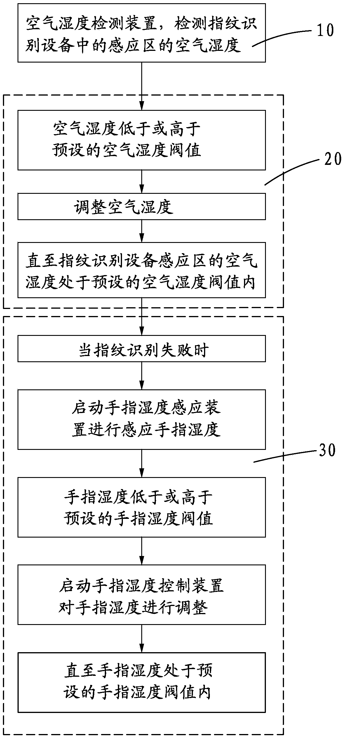
The invention provides a humidity control method of fingerprint recognition equipment. The method includes the steps that 10 the air humidity in an induction area of the fingerprint recognition equipment is detected through an air humidity detection device; 20 when the detected air humidity is lower than or higher than a preset air humidity threshold, an air humidity control device is started to conduct regulation on the air humidity of the induction area of the fingerprint recognition equipment until the air humidity of the induction area of the fingerprint recognition equipment is in the preset air humidity threshold. According to the humidity control method, the fingerprint recognition equipment can be prevented from being too wet, dehumidification can further be conducted on the fingers of a human body, and therefore the problem that humidity in the use environment of the fingerprint recognition equipment is too high is solved fundamentally.

Description

technical field [0001] The invention relates to a humidity control method and system of a fingerprint identification device. Background technique [0002] At present, most of the fingerprint identification modules have certain requirements for the use environment, and the environment with too high or too low humidity will cause the fingerprint identification device to fail to work normally. Moisture mainly comes from two sources: one is due to the influence of the weather, so that the humidity of the air is too high or too low, and the other is the human body characteristics and other reasons that cause fingers to sweat, or activities such as washing hands make fingers stained with water, etc. Humidity is too high. For the above problems, there is currently no solution on the market to specifically solve the problem of excessive humidity. [0003] The Chinese utility model published on 2011-01-05 with the publication number 201698505U discloses a protective box for fingerp...

Claims


Application Information

Patent Timeline
IPC IPC(8): G05D22/02
Inventor 陈风吴振文
Owner FUJIAN STAR NET EVIDEO INFORMATION SYST CO LTD
Learn More