
Display method and electronic equipment

A technology of electronic equipment and display method, applied in the direction of digital output to display equipment, TV, electrical components, etc., can solve the problem that users cannot distinguish the projected content and so on

Active Publication Date: 2014-12-03
LENOVO (BEIJING) LTD
View PDF4 Cites 3 Cited by
  • Summary
  • Abstract
  • Description
  • Claims
  • Application Information

AI Technical Summary

Problems solved by technology

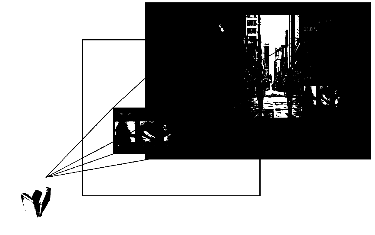
When the projected screen is smaller, if the same projected content and layout are still displayed as on the larger screen, it may cause users to be visually unable to distinguish the projected content
There is no method in the prior art that can adaptively adjust the content and layout of projected images

Method used


Image

  • Display method and electronic equipment
  • Display method and electronic equipment
  • Display method and electronic equipment

Examples


Embodiment Construction

[0049] Embodiments of the present invention provide a display method and an electronic device, which can adaptively adjust a projection display mode, and adjust display content and layout according to different acquired projection parameters, thereby improving user experience.

[0050] In order to enable those skilled in the art to better understand the technical solutions in the present invention, the technical solutions in the embodiments of the present invention will be clearly and completely described below in conjunction with the drawings in the embodiments of the present invention. Obviously, the described The embodiments are only some of the embodiments of the present invention, not all of them. Based on the embodiments of the present invention, all other embodiments obtained by persons of ordinary skill in the art without making creative efforts shall fall within the protection scope of the present invention.

[0051] see figure 1 , is a flow chart of the first embodi...


PUM


Abstract

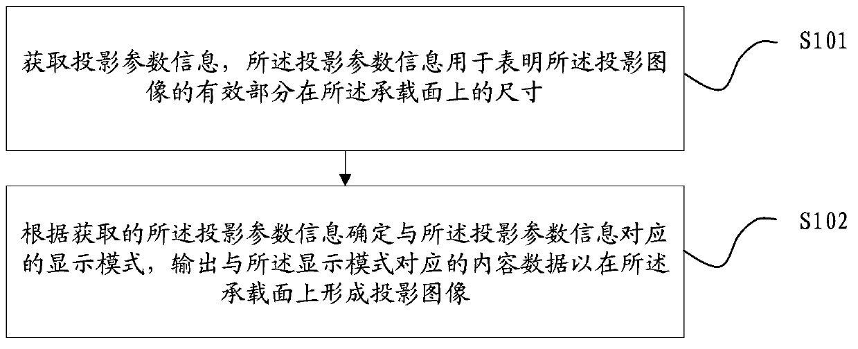
The invention relates to the electronic equipment field, especially to a display method and electronic equipment. The method is applied to first electronic equipment with a projection display unit; and the projection display unit is used for forming a projection image at a bearing surface when the bearing surface is located at a projection area of the projection display unit. The method comprises the following steps that: projection parameter information is obtained, wherein the projection parameter information is used for indicating the dimension of an effective portion of the projection image at the bearing surface; according to the obtained projection parameter information, a display mode corresponding to the projection parameter information is determined and content data corresponding to the display mode are outputted, thereby forming a projection image at the bearing surface. The first electronic equipment has at least two display modes including a first display mode and a second display mode; and in the first display mode, the first electronic equipment at least outputs first content data; and in the second display mode, the first electronic equipment at least outputs second content data. And the first content data are different from the second content data.

Description

technical field [0001] The invention relates to the field of electronic equipment, in particular to a display method and electronic equipment. Background technique [0002] With the development of display technology, many electronic devices have a projection module, which can conveniently project an image onto a projection plane for extended display. As the projection distance increases, electronic devices can be used to project screens of different sizes, for example, a 5-inch screen or a 30-inch screen can be projected. However, the displayed projected image content and layout are the same whether it is a smaller projection screen or a larger projection screen. When the projection screen is small, if the same projection content and layout as those on the larger screen are still displayed, it may cause users to be visually unable to distinguish the projection content. There is no method for adaptively adjusting the content and layout of projected images in the prior art. ...

Claims


Application Information

Patent Timeline
Patent Type & Authority Applications(China)
IPC IPC(8): H04N5/74G06F3/14
Inventor 张晓平王哲鹏武亚强曹璐
Owner LENOVO (BEIJING) LTD
Learn More